200
FX3U Series Programmable Controllers
User’s Manual - Hardware Edition
11 Use of High-speed Counters (C235 to C255)
11.10 Examples of External Wiring (Rotary Encoder)
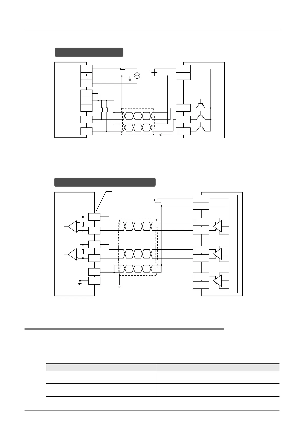
2) PNP open collector transistor output rotary encoder
2. When high-speed input special adapter (FX3U-4HSX-ADP) is used
1) Differential line driver output rotary encoder
11.10.3 Cautions for the other side device
Encoders having the output forms shown in the following table can be connected to the terminals. (The
encoders may not function correctly depending on electrical compatibility. Check the specifications in
advance.)
Voltage output type encoders and absolute encoders cannot be connected to the high-speed counter input
terminals.
Terminal for connecting Output form that can be directly connected
Input terminals of main unit
Open collector transistor output form
(applicable to 24V DC)
Input terminals of FX
3U-4HSX-ADP
Differential line driver output form
Set the input voltage of FX
3U-4HSX-ADP to 5V DC or less.
* The grounding resistance should be 100
Ω
or less.
PLC
S/S
L
N
24V
0V
24V
Rotary encoder
24V DC
In the case of source wiring
0V
X000
X001
1.5
k
Ω
Phase A
Phase B
Phase Z
20mA or
more
Class D
grounding*
Fuse
In the case of differential line driver wiring
* The grounding resistance should be 100
Ω
or less.
High-speed input
special adapter
Class D
grounding*
Twisted-pair
shielded wire
Phase A-
-
+
Rotary encoder
Phase B+
Phase Z+
Phase A+
Phase B-
Phase Z-
X0/3-
X000
X0/3+
X000
Equivalent to
AM26C32
330
Ω
X1/4-
X001
X1/4+
X001
Equivalent to
AM26C32
330
Ω
SG
SG
Input No. of first/second
unit
Non-inverted
output
Inverted output
Non-inverted
output
Inverted output

 Loading...


