FX3U Series Programmable Controllers
User’s Manual - Hardware Edition
317
16 FX2N-8/16E*-*(Input/Output Extension Blocks)
16.11 FX2N-8EYT, FX2N-16EYT and FX2N-16EYT-C (Transistor Output)
11
High-Speed
Counters
12
Output Wiring
13
Wiring for
Various Uses
14
Test Run,
Maintenance,
Troubleshooting
15
IInput/Output
Powered
Extension Units
16
Input/Output
Extension
Blocks
17
Extension
Power Supply
Unit
18
Other Extension
Units and
Options
19
Display Module
20
Terminal Block
16.11 FX2N-8EYT, FX2N-16EYT and FX2N-16EYT-C (Transistor Output)
16.11.1 Product specifications
The generic specifications are identical to the main unit specifications.
→ Refer to Section 4.1 for generic specifications.
For external wiring, refer to the following chapter.
→ Refer to Chapter 12 for output wiring.
1. Power supply specifications
2. Weight and Other spesifications
3. Output specifications (Transistor output type)
Item FX2N-8EYT FX2N-16EYT FX2N-16EYT-C
Product type FX2N extension block FX2N connector type extension block
Rated voltage 24V DC (supplied from main unit and input/output powered extension unit)
Item FX2N-8EYT FX2N-16EYT FX2N-16EYT-C
MASS (Weight) 0.2 kg (0.44lbs) 0.3 kg (0.66lbs)
Other
• The extension cable is already connected to the extension block.
• Accessories: Label for indication of input/output number
• The DIN46277 rail (width: 35 mm (1.38")) or direct installation.
Item FX2N-8EYT FX2N-16EYT FX2N-16EYT-C
Output points 8 points 16 points
Connection unit Removable terminal block (M3 screws) Connector terminal block
Output unit/type Transistor/sink output
External power supply 5 to 30V DC
Output circuit insulation method Photo-coupler insulation
Indication of output operation Activation of the photo-coupler will light the LED indicator lamp on panel.
Maximum load
Resistance
load
0.5 A/point
The total load current per common
should be as follows:
• 4 output points/common: 0.8A or less
• 8 output points/common: 1.6A or less
0.3 A/point
The total load current per common
should be as follows:
• 16 output points/common: 1.6A or
less
Inductive load 12 W/24V DC 7.2 W/24V DC
Open circuit leakage current 0.1 mA/30 A DC
Minimum load −
Response time
OFF→ON 0.2 ms or less for 200 mA (at 24V DC)
ON→OFF 0.2 ms or less for 200 mA (at 24V DC)
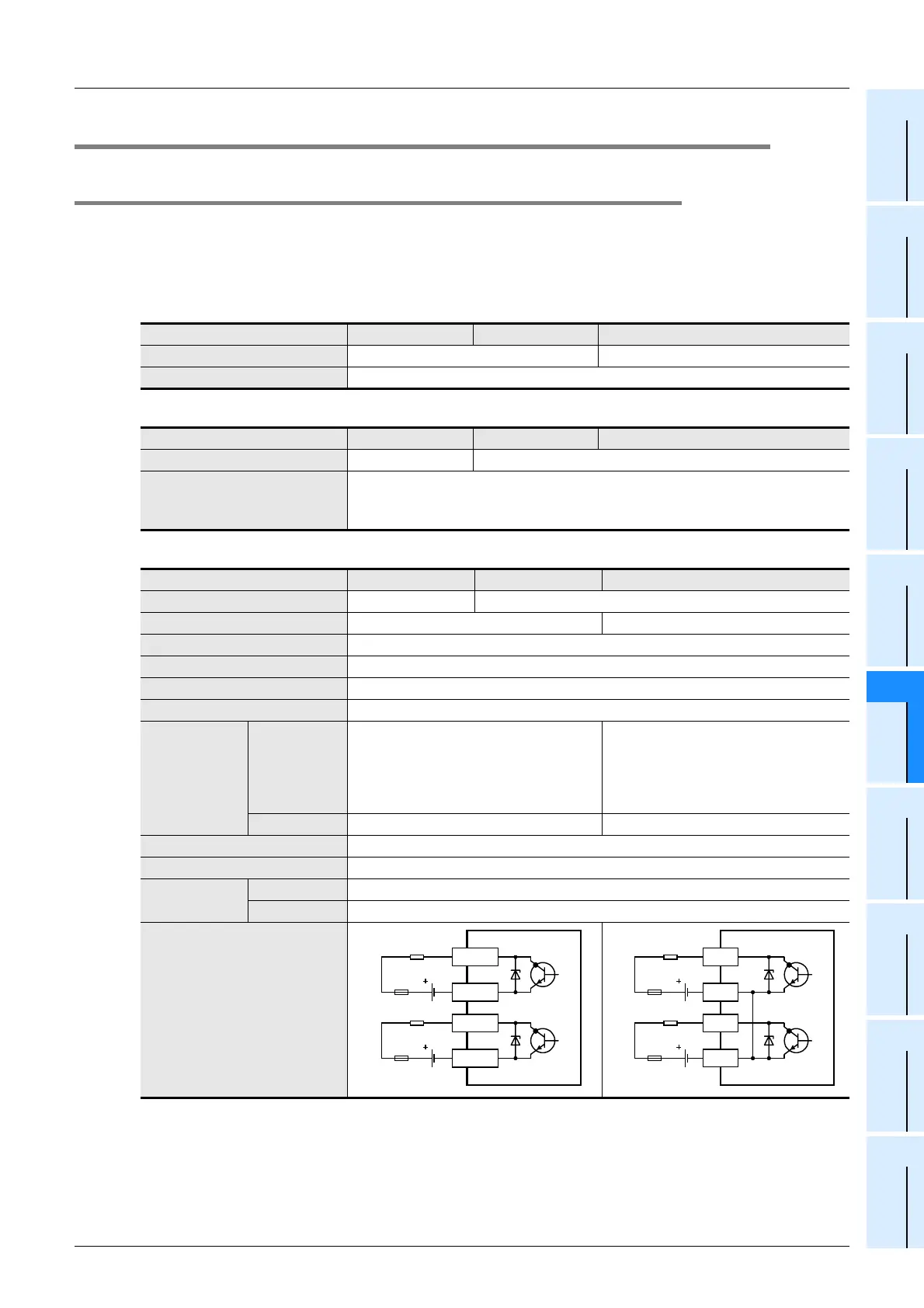
Output circuit diagram
Load
Fuse
DC power
supply unit
Fuse
DC power
supply unit
Y
COM1
Y
COM2
Load
Fuse
DC power
supply unit
Y
COM
Fuse
DC power
supply unit
Y
COM

 Loading...


