FX3U Series Programmable Controllers
User’s Manual - Hardware Edition
169
10 Input Wiring Procedures (Input Interruption and Pulse Catch)
10.2 24V DC Input Type (Common to Sink/Source Input)
1
Introduction
2
Features and
Part Names
3
Product
Introduction
4
Specifications
5
Version and
Peripheral
Devices
6
System
Configuration
7
Input/Output
Nos., Unit Nos.
8
Installation
9
Preparation and
Power Supply
Wiring
10
Input Wiring
Cautions in wiring when changing filter time
When setting the input filter to 5µs or capturing pulses of a response frequency of 50 to 100kHz with a high-
speed counter, wire the terminals as stated below.
1) The wiring length should be 5m or less.
2) Connect a bleeder resistance of 1.5kΩ (1 W or more) to the input terminal, so that the sum of the load
current of the open collector transistor output on the mating device and the input current of the main body
is 20 mA or more.
3. Input sensitivity
The PLC input current and input sensitivity are shown in the following table.
When there is a series diode or resistance at the input contact or there is a parallel resistance or leakage
current at the input contact, wire the terminals in accordance with the following table.
→ For the instructions for connecting input devices, refer to Subsection 10.2.3.
4. Examples of input wiring
For the wiring of input interruption, pulse catch and rotary encoder, refer to the following sections.
→ Example of wiring of input interruption: Refer to Section 10.4.
→ Example of wiring of pulse catch: Refer to Section 10.5.
→ Example of wiring of rotary encoder: Refer to Section 11.10.
10.2.3 Instructions for connecting input devices
1. In the case of no-voltage contact
The input current of this PLC is 5 to 7 mA/24V DC.
Use input devices applicable to this minute current.
If no-voltage contacts (switches) for large current are used, contact failure may occur.
<Example> Products of OMRON
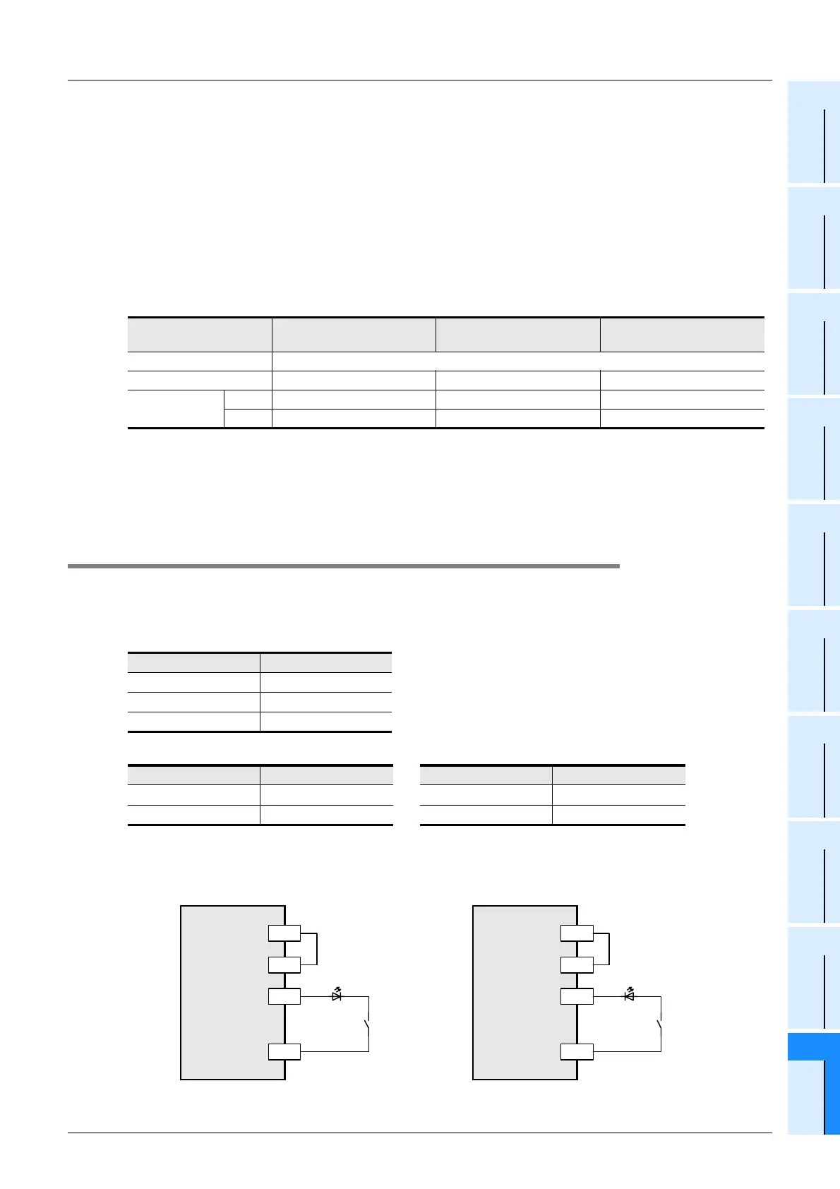
2. In the case of input device with built-in series diode
The voltage drop of the series diode should be approx. 4V or less.
When lead switches with a series LED are used, up to two switches can be connected in series.
Also make sure that the input current is over the input-sensing level while the switches are ON.
Item X000 to X005 X006 to X007
X010 to max input number
of the main unit
Input voltage AC power type: 24V DC ±10% DC power type: 16.8 to 28.8V DC
Input current 6 mA 7 mA 5 mA
Input sensitivity
current
ON 3.5 mA or more 4.5 mA or more 3.5 mA or more
OFF 1.5 mA or less 1.5 mA or less 1.5 mA or less
Input number Input current
X000 to X005 6 mA/24V DC
X006, X007 7 mA/24V DC
X010 or more 5 mA/24V DC
Type Model name Type Model name
Microswitch Models Z, V and D2RV Operation switch Model A3P
Proximity switch Model TL Photoelectric switch Model E3S
PLC
(source input)
X
24V
LED
*1 In the case of a type only for sink input,
connect the device to the COM terminal.
PLC
(sink input)
X
0V
LED
*1
24V
S/S S/S
0V

 Loading...


