FX3U Series Programmable Controllers
User’s Manual - Hardware Edition
129
8 Installation In Enclosure
8.3 Layout in Enclosure
1
Introduction
2
Features and
Part Names
3
Product
Introduction
4
Specifications
5
Version and
Peripheral
Devices
6
System
Configuration
7
Input/Output
Nos., Unit Nos.
8
Installation
9
Preparation and
Power Supply
Wiring
10
Input Wiring
8.3 Layout in Enclosure
The PLC components can be laid out in one stage or in two stages, upper and lower. The connecting
procedures in each case are explained below.
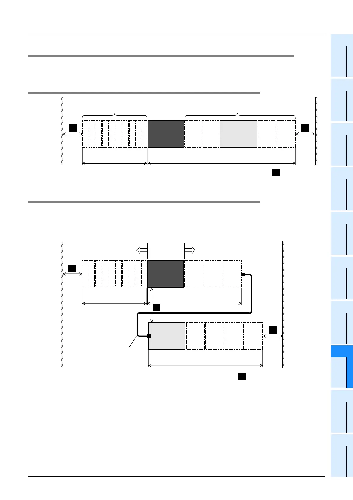
8.3.1 1-stage layout
8.3.2 2-stage layout
In the case of a 2-stage layout, connect the first stage and the second stage with the extension cable.
When an extension block is connected at the top of the second stage, FX
2N-CNV-BC (connector conversion
adapter) is necessary.
1. When an input/output powered extension unit is connected at the top of the 2nd stage
Input/output powered extension units/blocks
Special function units/blocks
FX
3U
Series
main unit
Input/output
powered
extension units
For the dimensions of each product, refer to the
external dimensions diagram.
Special adapter
12345678
Up to 10 units (approx.
18 mm(0.71") x number of units)
910
Extension
block
Extension
block
Extension
block
Extension
block
A
≥
50mm (1.97")
A A
Input/output powered extension
units/blocks
Special function units/blocks
FX
3U
Series
main unit
For the dimensions of each product, refer to the
external dimensions diagram.
Special adapter
Input/output
powered
extension
units
*1
For the dimensions of each product, refer to the
external dimensions diagram.
Extension cable
•
FX
0N
-65EC (650mm (25.59"))
•
FX
0N
-30EC (300mm (11.81"))
12345678
Up to 10 units (approx. 18mm
(0.71") x number of units)
910
Extension
block
Extension
block
Extension
block
Extension
block
Extension
block
Extension
block
Extension
block
*1 The shaded part in the above figure includes FX
2N
-1RM(-E)-SET
and FX
3U
-1PSU-5V, however only FX
2N
-1RM(-E)-SET is
connectable to FX
2N
-1RM(-E)-SET.
A
≥
50mm (1.97")
A
A
A

 Loading...


