FX3U Series Programmable Controllers
User’s Manual - Hardware Edition
236
13 Examples of Wiring for Various Uses
13.6 Seven Segment with Latch [SEGL Instructions (FNC74)/BCD Instructions (FNC18)]
13.6 Seven Segment with Latch [SEGL Instructions (FNC74)/BCD
Instructions (FNC18)]
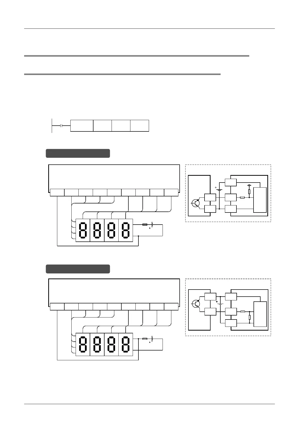
13.6.1 When SEGL instructions are used
This subsection gives examples of wiring for displaying the current value of D100 on the 4-digit 7-segment
display.
1. Main Unit
Example of program
Example of wiring
M8000
D100 Y010 K1SEGL
10
3
10
2
10
1
10
0
124
8
10
3
10
2
10
1
10
0
1
2
4
Y010COM3 Y011 Y012 Y013 Y014 Y015 Y016 Y017
8
Transistor output (sink)
*
* Use a 7-segment display with a latch and a built-in BCD decoder.
Main unit (Ex: FX
3U
-32MT/ES)
Signal
-
Internal
circuit
7-segment display
+
Y
COM1
PLC
7-segment display to be used for sink wiring
(in the case of transistor output)
In the case of sink wiring
10
3
10
2
10
1
10
0
124
8
10
3
10
2
10
1
10
0
1
2
4
Y010+V2 Y011 Y012 Y013 Y014 Y015 Y016 Y017
8
Transistor output (source)
*
* Use a 7-segment display with a latch and a built-in BCD decoder.
Signal
-
Internal
circuit
7-segment display
+
Y
PLC
7-segment display to be used for source wiring
(in the case of transistor output)
+V0
Main unit (Ex: FX
3U
-32MT/ESS)
In the case of source wiring

 Loading...


