424
FX3U Series Programmable Controllers
User’s Manual - Hardware Edition
20 FX-16/32E*-*-TB (Terminal Block)
20.8 FX-16EYT-TB, FX-16EYT-H-TB
20.8 FX-16EYT-TB, FX-16EYT-H-TB
The FX-16EYT(-H)-TB is used by connecting it to the FX2N series output extension block (transistor).
The applications shown below are not supported.
20.8.1 Specifications
*1. This response time does not include the response delay at the PLC.
Output Connector
Connectable models FX
2N-16EYT-C (sink output)
Unsupported Applications
Pulse
outputs
Pulse Y output (PLSY) instruction, acceleration/deceleration setup (PLSR) instruction, pulse width
modulation (PWM) instruction, DOG search zero return (DSZR) instruction, interruption positioning
(DVIT) instruction, batch data positioning mode (TBL) instruction, absolute current value read (ABS)
instruction, zero return (ZRN) instruction, variable speed pulse output (PLSV) instruction, drive to
increment (DRVI) instruction, drive to absolute (DRVA) instruction
Time division
input
Input matrix (MTR) instruction, hexadecimal input (HKY) instruction, digital switch (DSW) instruction,
arrow switch (ARWS) instruction
Time division
output
Seven segment with latch (SEGL) instruction, print (ASCII Code) (PR) instruction
Item
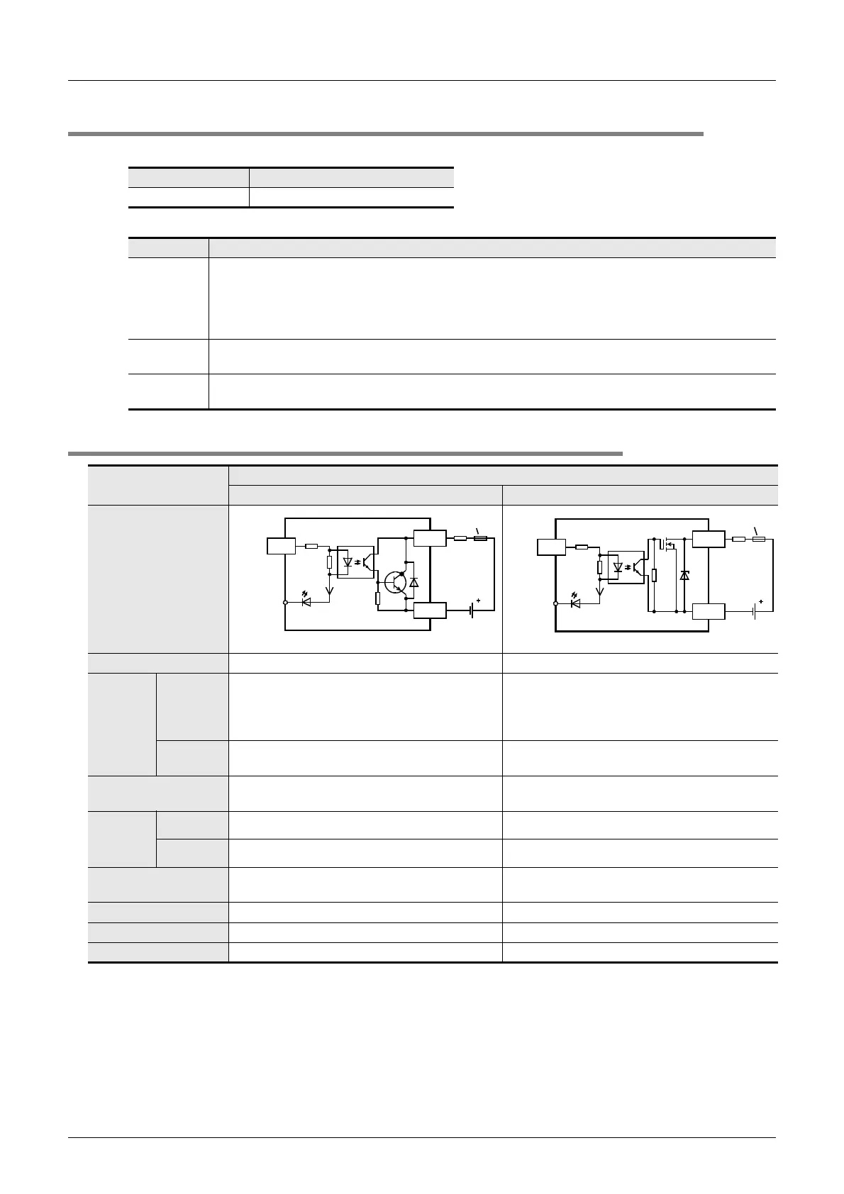
Transistor output
FX-16EYT-TB FX-16EYT-H-TB
Input/output circuitry
Load voltage 5 to 30V DC 5 to 30V DC
Max. load
Resistance
load
0.5 A / point
The total load current of resistance loads per
common terminal should be the following value.
• 4 output points/common terminal: 0.8A or less
1 A / point
The total load current of resistance loads per
common terminal should be the following value.
• 4 output points/common terminal: 3A or less
Inductive
load
12 W/24V DC 24 W/24V DC
Open-circuit leakage
current
0.1 mA / 30V DC 0.1 mA / 30V DC
Response
time
*1
OFF→ON
*1
0.2 ms or less / 24V DC 0.3 ms or less / 24V DC
ON→OFF
*1
1.5 ms or less / 24V DC 4 ms or less / 24V DC
Output element’s ON
voltage
1.5 V 1.5 V
Circuit isolation Photo-coupler isolation Photo-coupler isolation
Operation indicators LED lights when photo-coupler power is supplied LED lights when photo-coupler power is supplied
Power consumption 2.7 W (112 mA 24V DC) 2.7 W (112 mA 24V DC)
Photo-
coupler
3.3k
Ω
LED
24V DC
7mA
5 to 30V
DC
0 to 7
COMn
Fuse
CN1
Connector
side
External
wiring
24+
Photo-
coupler
LED
0 to 7
COMn
Fuse
CN1
Connector
side
3.3k
Ω
24V DC
7mA
External
wiring
5 to 30V
DC
24+

 Loading...


