FX3U Series Programmable Controllers
User’s Manual - Hardware Edition
357
19 FX3U-7DM (Display Module)
19.7 Monitor/Test Mode [Excluding User-Registered Devices]
11
High-Speed
Counters
12
Output Wiring
13
Wiring for
Various Uses
14
Test Run,
Maintenance,
Troubleshooting
15
IInput/Output
Powered
Extension Units
16
Input/Output
Extension
Blocks
17
Extension
Power Supply
Unit
18
Other Extension
Units and
Options
19
Display Module
20
Terminal Block
19.7 Monitor/Test Mode [Excluding User-Registered Devices]
19.7.1 Relevant devices
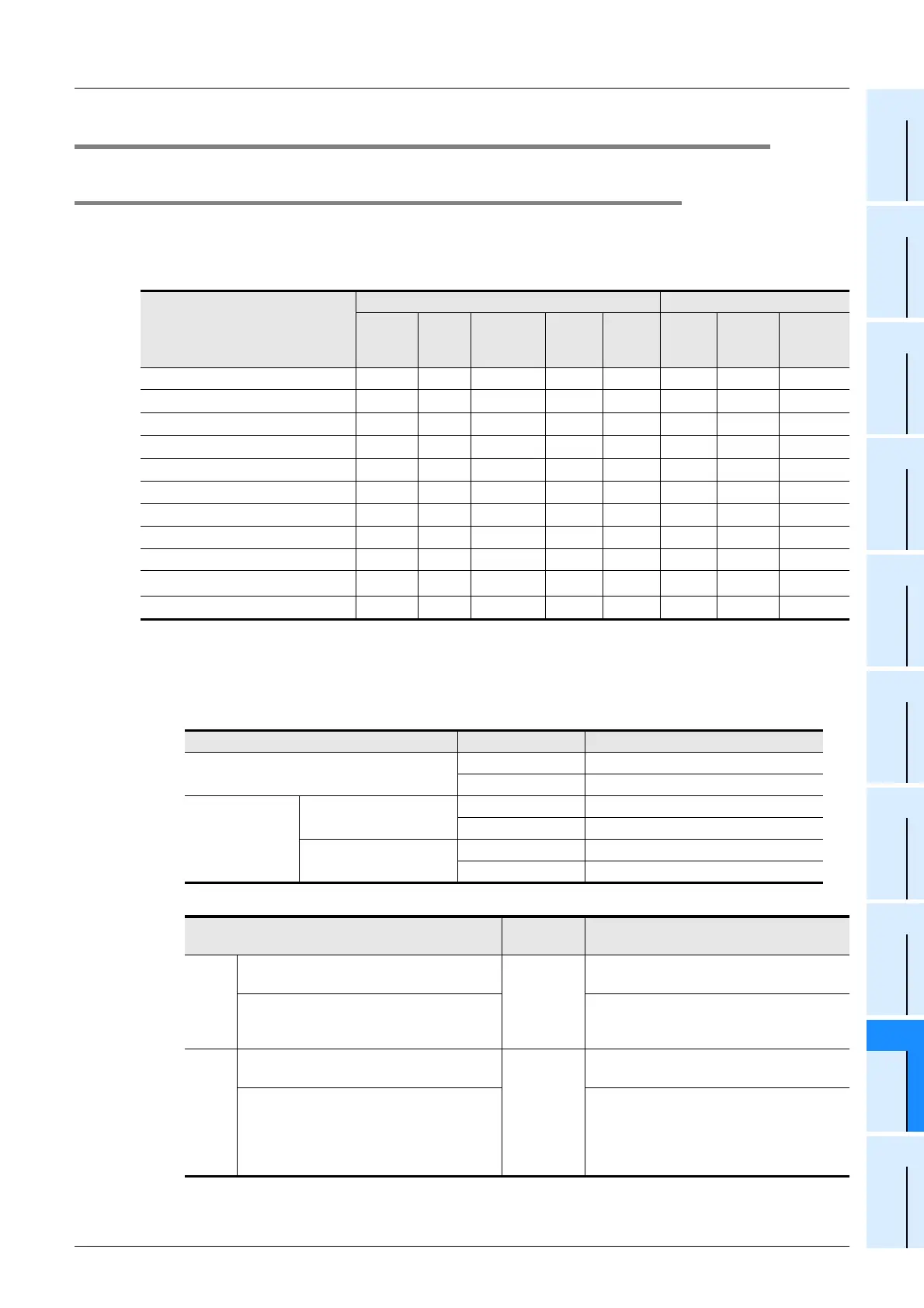
Monitoring and testing can be performed from the "Monitor/Test" menu for the devices listed below.
(Monitoring/testing is not possible for the file register (D) and the index register (V/Z)).
*1. A forced ON or OFF is executed for only one operation cycle, and therefore has a considerable effect
on the SET/RST and self retaining circuits when the PLC is running.
Moreover, a forced ON/OFF result is retained for devices (Y,M,S) which are not being driven by an
OUT instruction, etc., in the program.
*2. Setting values of timer and counter can be changed when the PLC status is as shown below.
*3. The following setting changes are possible.
*4. The C200 to C255 32-bit up/down counters and the high-speed counters have counting directions.
*5. Enabled only when a memory cassette is installed.
: Possible : Possible under certain conditions
: Not possible −: Item not supported by this device
Device
Monitored Items Test Items
Contact Reset
Operation
Direction
Current
Value
Setting
Value
Forced
ON/
OFF
Current
Value
Change
Setting
Change
Input [X] − − −−− − −
Output [Y] −− −−
*1
−−
Auxiliary relay [M] −− −−
*1
−−
State [S] −− −−
*1
−−
Timer [T] −
*2*3
Counter [C]
*4
*2*3
Data register [D, DD] −− − −− −
File register [D, DD] −− −
−−
−
Extended register [R, DR] −− − −− −
Extended file register [ER, DER]
*5
−− − −− −
Index register (V,Z) −− −
−−
−
Program Memory Type RUN/STOP Status Setting Change Enabled/Disabled
Internal RAM
RUN Enabled
STOP Enabled
Memory cassette
PROTECT switch ON
RUN Disabled
STOP Disabled
PROTECT switch OFF
RUN Enabled
STOP Enabled
Selectable Setting Values
Changeable
Content
Setting Description
Direct
setting
Without index modifier [Direct (K,H)]
Direct
numeral
setting
The directly specified value becomes the
setting value.
With index modifier [direct (K,H) + index
register (V0 to V7, Z0 to Z7)]
The [directly specified numerical value] +
[index register’s current value] becomes
the setting value.
Indirect
setting
Without index modifier
[data register D, extended register (R)]
Indirectly
specified
device No.
The specified device’s current value
becomes the setting value.
With index modifier
[data register (D) + index register (V0 to
V7, Z0 to Z7)],
[Extended register (R) + index register (V0
to V7, Z0 to Z7)]
The [directly specified device No.] + [index
register’s current value] becomes the
device No. specified by the setting value.
That device’s current value becomes the
setting value.

 Loading...


