198
FX3U Series Programmable Controllers
User’s Manual - Hardware Edition
11 Use of High-speed Counters (C235 to C255)
11.10 Examples of External Wiring (Rotary Encoder)
11.10 Examples of External Wiring (Rotary Encoder)
11.10.1 1-phase 1-input [C235 to C245]
The following examples of wiring apply to the cases where C235 is used. When another high-speed counter
number is used, wire the counter referring to the following diagrams.
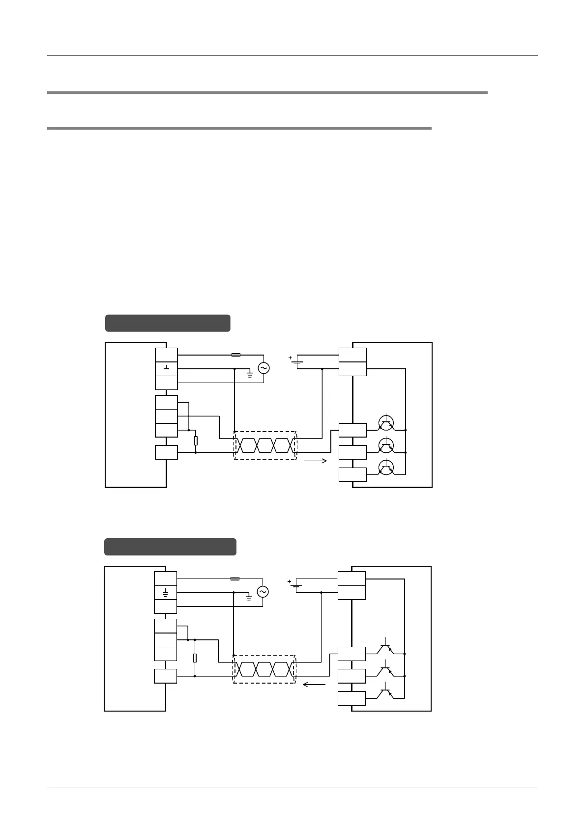
1. When the input terminals of the main unit are used
When pulses having a response frequency of 50 k to 100 kHz are captured to the high-speed counter using
the input terminals X000 to X005, wire the counter as stated below.
• The wiring length should be 5m (16’4") or less.
• As connecting cables, use shielded twisted-pair cables. Ground the shield of each shielded cable only on
the PLC side.
• Connect a bleeder resistance of 1.5kΩ (1W or more) to the input terminal, so that the sum of the load
current of the open collector transistor output on the mating device side and the input current of the main
unit is 20 mA or more.
1) NPN open collector transistor output rotary encoder
2) PNP open collector transistor output rotary encoder
* The grounding resistance should be 100
Ω
or less.
PLC
S/S
L
N
24V
0V
24V
Rotary encoder
Class D
grounding*
Fuse
24V DC
In the case of sink wiring
0V
X000
1.5k
Ω
Phase A
Phase B
Phase Z
20mA or
more
* The grounding resistance should be 100
Ω
or less.
PLC
S/S
L
N
24V
0V
24V
Rotary encoder
Class D
grounding*
Fuse
24V DC
In the case of source wiring
0V
X000
1.5
k
Ω
Phase A
Phase B
Phase Z
20mA or
more

 Loading...


