FX3U Series Programmable Controllers
User’s Manual - Hardware Edition
179
10 Input Wiring Procedures (Input Interruption and Pulse Catch)
10.4 Input Interruption (I00
to I50
) - With Delay Function
1
Introduction
2
Features and
Part Names
3
Product
Introduction
4
Specifications
5
Version and
Peripheral
Devices
6
System
Configuration
7
Input/Output
Nos., Unit Nos.
8
Installation
9
Preparation and
Power Supply
Wiring
10
Input Wiring
10.4 Input Interruption (I00 to I50) - With Delay Function
The PLC (main unit) is provided with an input interruption function (input delay interruption function) and has
six interruption input points.
The ON or OFF duration of interruption input signals should be 5µs or more.
→ For details on programming, refer to the programming manual.
10.4.1 Allocation of pointers to input numbers (input signal ON/OFF duration)
10.4.2 Input interruption delay function
This input interruption has a function to delay execution of interruption routine in 1ms units.
With this delay function, the position of the sensor used for input interruption can be adjusted in the sequence
program. It is necessary to adjust the actual position of the sensor.
→ For the programming, refer to the programming manual.
10.4.3 Cautions for input interruption
1. Non-overlap of of input numbers
The input terminals X000 to X007 can be used for high-speed counter, input interruption, pulse catch, SPD,
ZRN, DSZR and DVIT instructions and general-purpose inputs.
Take care not to overlap the input numbers.
Example:
When the input interrupt pointer "I001" is used, X000 is occupied. Therefore, it is impossible to use C235,
C241, C244, C246, C247, C249, C252 and C254, input interruption (including delay interruption) pointer I000,
pulse catch contact M8170 and SPD, ZRN, DSZR and DVIT instructions at the same time.
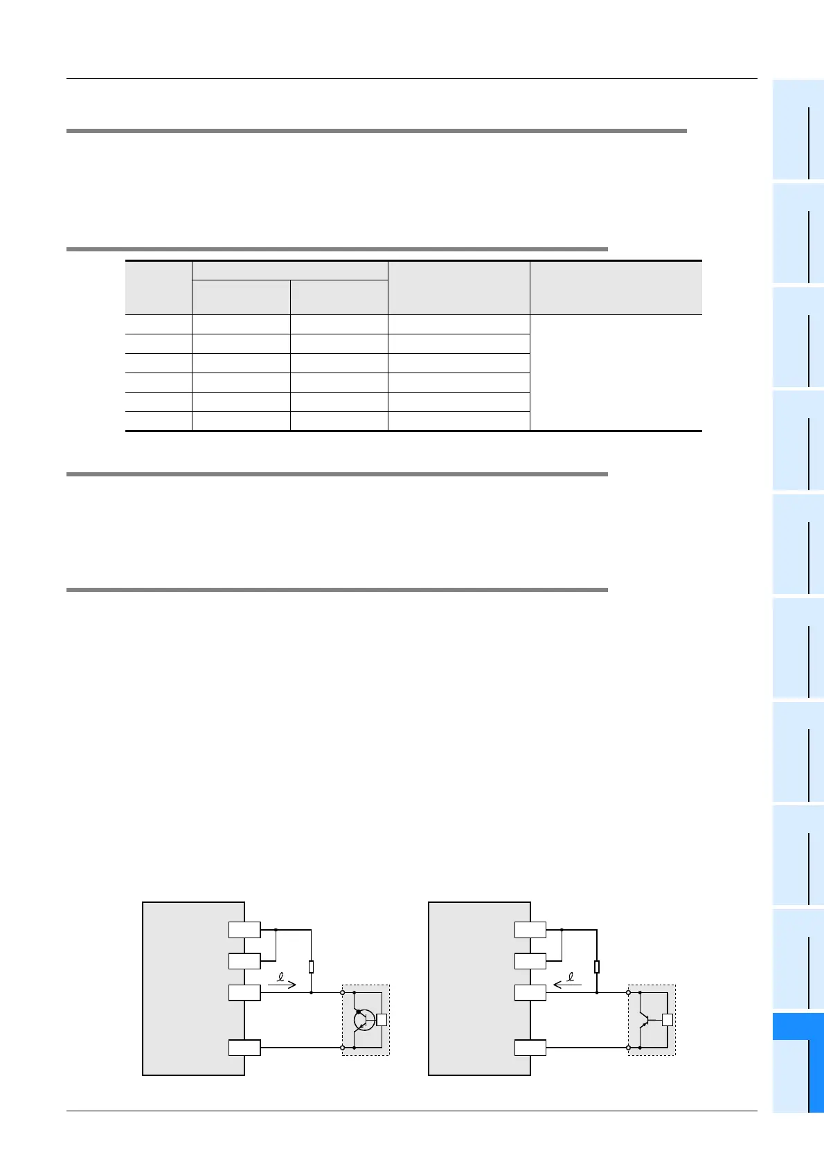
2. Cautions in wiring
• The wiring length should be 5m or less.
• Connect a bleeder resistance of 1.5kΩ (1 W or more) to the input terminal, so that the sum of the load
current of the open collector transistor output on the other side device and the input current of the main
body is 20 mA or more.
- Source input: PNP open collector transistor
- Sink input: NPN open collector transistor
Input No.
Interrupt pointer
Interrupt disable
control
ON or OFF duration of input
signal
Interruption on
leading edge
Interruption on
trailing edge
X000 I001 I000 M8050
5µs or more
X001 I101 I100 M8051
X002 I201 I200 M8052
X003 I301 I300 M8053
X004 I401 I400 M8054
X005 I501 I500 M8055
PLC
(source input)
X
24V
Rb
I
PLC
(sink input)
X
0V
Rb
I
2-wire
proximity
sensor
24V
S/S S/S
0V
Bleeder
resistance
Bleeder
resistance
2-wire
proximity
sensor

 Loading...


