283
FX3U Series Programmable Controllers
User’s Manual - Hardware Edition
15 FX2N-32/48E*-* (Input/Output Powered Extension Units)
15.8 FX2N-48ER-UA1/UL
11
High-Speed
Counters
12
Output Wiring
13
Wiring for
Various Uses
14
Test Run,
Maintenance,
Troubleshooting
15
IInput/Output
Powered
Extension Units
16
Input/Output
Extension
Blocks
17
Extension
Power Supply
Unit
18
Other Extension
Units and
Options
19
Display Module
20
Terminal Block
15.8 FX2N-48ER-UA1/UL
15.8.1 Product specifications
The generic specifications are the same as those for the main unit.
→ For the generic specifications, refer to Section 4.1.
For external wiring, refer to the following chapters.
→ Refer to Chapter 9 for power supply wiring.
→ Refer to Chapter 10 for input wiring.
→ Refer to Chapter 12 for output wiring.
1. Power supply specifications
→ For the power supply specifications, refer to Section 15.2.
2. Input specifications (100V AC Input)
Item FX2N-48ER-UA1/UL
Number of input points 24 points
Connection type Removable terminal block (M3 screw)
Input form AC input
Input signal voltage 100 to 120V AC +10%,-15% 50/60 Hz
Input signal current
4.7 mA/100V AC 50 Hz (70% or less when turned on simultaneously)
6.2 mA/110V AC 60 Hz (70% or less when turned on simultaneously)
Input impedance
Approx. 21 kΩ/50 Hz
Approx. 18 kΩ/60 Hz
Input sensitivity
current
Input ON
current
3.8 mA or more/80V AC
Input OFF
current
1.7 mA or less/30V AC
Input response time Approx. 25 to 30 ms
Input signal form Contact input
Input circuit insulation Photocoupler insulation
Indication of input operation LED on panel is lit when there is input.
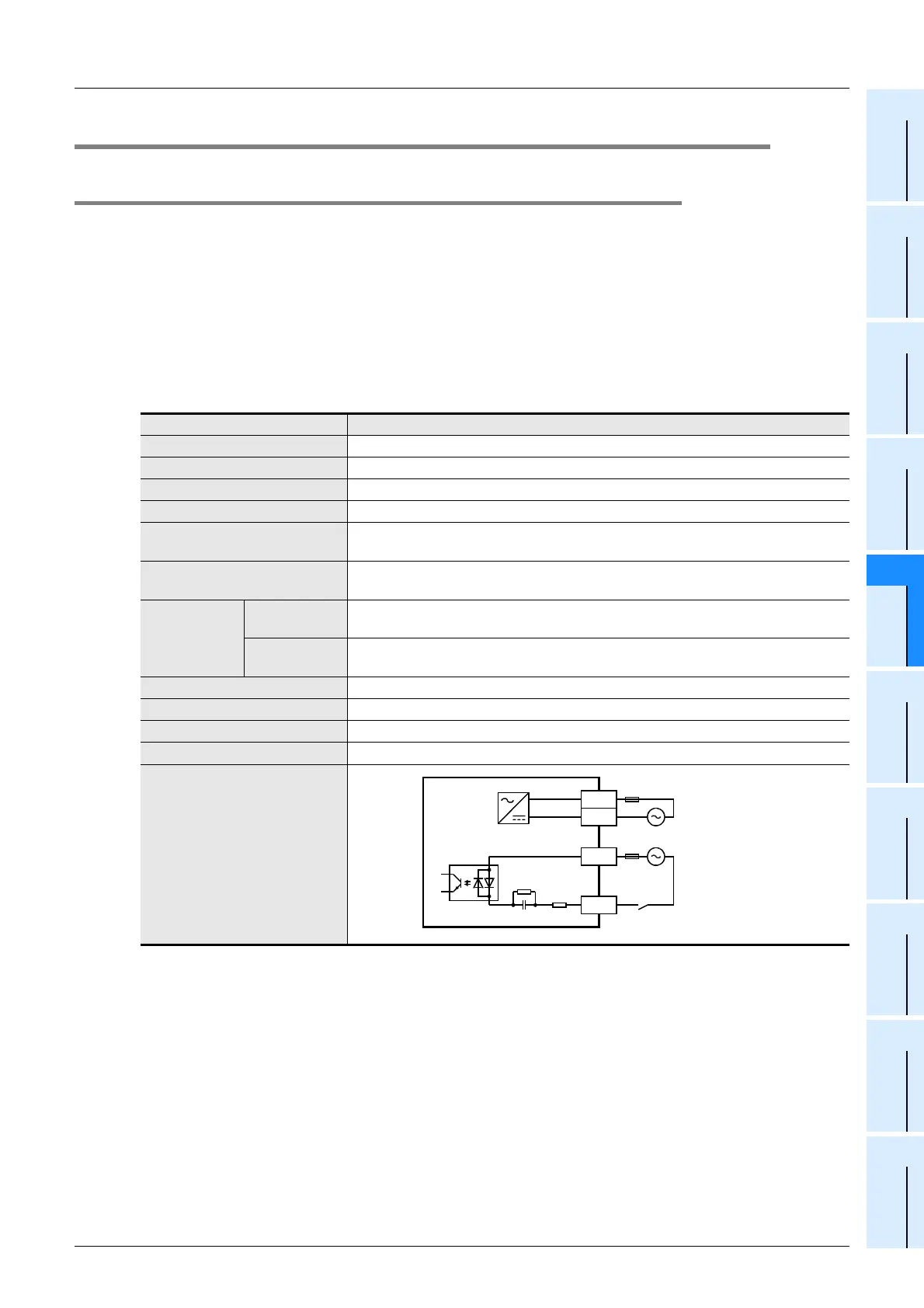
Input circuit diagram
N
L
100 to 240V AC
Fuse
X
COM
*1
*1 Input impedance

 Loading...


