FX3U Series Programmable Controllers
User's Manual - Hardware Edition
32
2 Features and Part Names
2.2 Names and Functions of Parts
2.2 Names and Functions of Parts
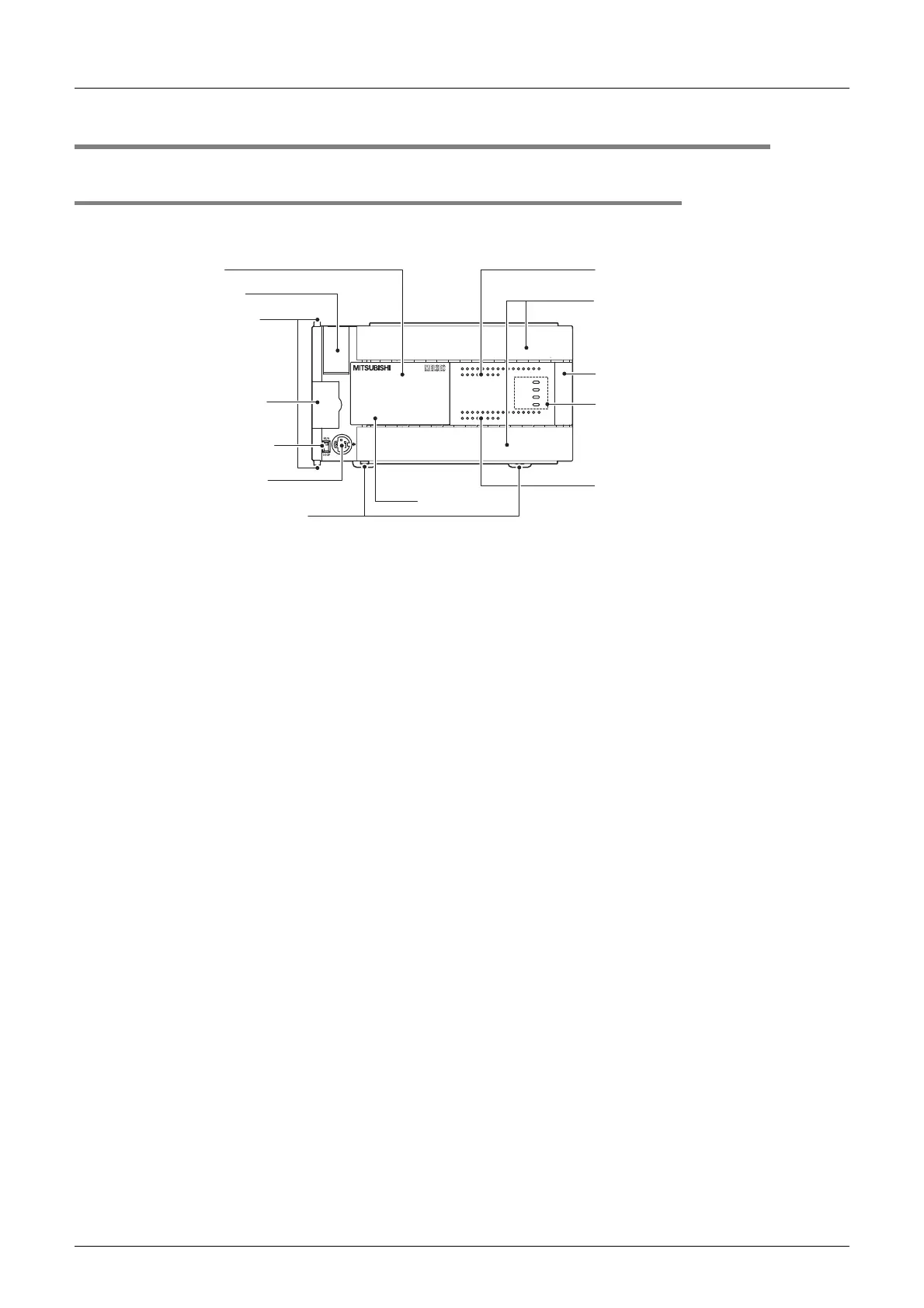
2.2.1 Front Panel
Factory default configuration (standard)
[1]
Top cover Mount the memory cassette under this cover.
When FX
3U-7DM (display module) is used, replace this cover with the
cover supplied with FX
3U-7DM.
[2]
Battery cover The battery (standard accessory) is set under this cover. When replacing
it with a new one, open this cover.
[3]
Special adapter connecting
hooks (2 places)
When connecting the special adapter, secure it with these hooks.
[4]
Expansion board dummy cover Remove this dummy cover, and mount an expansion board.
[5]
RUN/STOP switch To stop writing (batch) of the sequence program or operation, set the
switch to STOP (slide it downward).
To start operation (run the machine), set it to RUN (slide it upward).
[6]
Peripheral device connecting
connector
Connect a programming tool to program a sequence.
→ For details on applicable peripheral devices,
refer to Chapter 5.
[7]
DIN rail mounting hooks The main unit can be installed on DIN46277 rail (35 mm (1.38") wide).
[8]
Model name (abbreviation) The model name of the main unit is indicated.
Check the nameplate on the right side for the model name.
[9]
Input display LEDs (red) When an input terminal (X000 or more) is turned on, the corresponding
LED lights.
[10]
Terminal block covers The covers can be opened about 90° for wiring.
Keep the covers closed while the PLC is running (the unit power is on).
[11]
Extension device connecting
connector cover
Connect the extension cables of input/output powered extension unit/
block or special function unit/block to the extension device connecting
connectors under this cover.
FX
3U Series extension devices, FX2N Series extension devices and FX0N
Series extension devices can be connected.
→ For details on the extension devices, refer to
Chapter 15, Chapter 16 and Section 18.1.
FX
3U
-48MR/ES
FX
3U
-48MFX
3U
ERROR
RUN
BATT
POWER
R
0312
IN
OUT
645
21
7
20 2422 23 2625
10 11 1312 1614 15 17
27
2120 2422 23 2625
10 11 1312 1614 15 17
27
Y12Y10 Y16Y14 Y22Y20 Y26 COM5
COM1
Y24Y6
Y4Y2Y0
Y7 Y11 Y13Y5
COM2
Y3
Y1
COM3 Y15 Y17COM4 Y23 Y25 Y27Y21
X5
X0
X1
X2
X3 X7
X11
X13
X40VS/S
N 24V
X6 X10 X12 X14 X16 X20
L X27X23 X25X15 X17 X21
X24 X26X22
FX
3U
-48MR/ES
FX
3U
-48MFX
3U
ERROR
RUN
BATT
POWER
R
0312
IN
OUT
645
21
7
20 2422 23 2625
10 11 1312 1614 15 17
27
0312 645
21
7
20 2422 23 2625
10 11 1312 1614 15 17
27
Y12Y10 Y16Y14 Y22Y20 Y26 COM5
COM1
Y24Y6
Y4Y2Y0
Y7 Y11 Y13Y5
COM2
Y3
Y1
COM3 Y15 Y17COM4 Y23 Y25 Y27Y21
X5
X0
X1
X2
X3 X7
X11
X13
X40VS/S
N 24V
X6 X10 X12 X14 X16 X20
L
X27X23 X25X15 X17 X21
X24 X26X22
[1] Top cover
[2] Battery cover
[3] Special adapter
connecting hooks
[9] Input display LEDs
[10] Terminal block covers
[11] Extension device connecting
connector cover
[12] Operation status display LEDs
[13] Output display LEDs
[8] Model name
[4] Expansion board
dummy cover
[5] RUN/STOP switch
[6] Peripheral device
connecting connector
[7] DIN rail mounting hooks

 Loading...


