FX3U Series Programmable Controllers
User’s Manual - Hardware Edition
143
8 Installation In Enclosure
8.7 Connecting Methods for Main Unit and Extension Devices
1
Introduction
2
Features and
Part Names
3
Product
Introduction
4
Specifications
5
Version and
Peripheral
Devices
6
System
Configuration
7
Input/Output
Nos., Unit Nos.
8
Installation
9
Preparation and
Power Supply
Wiring
10
Input Wiring
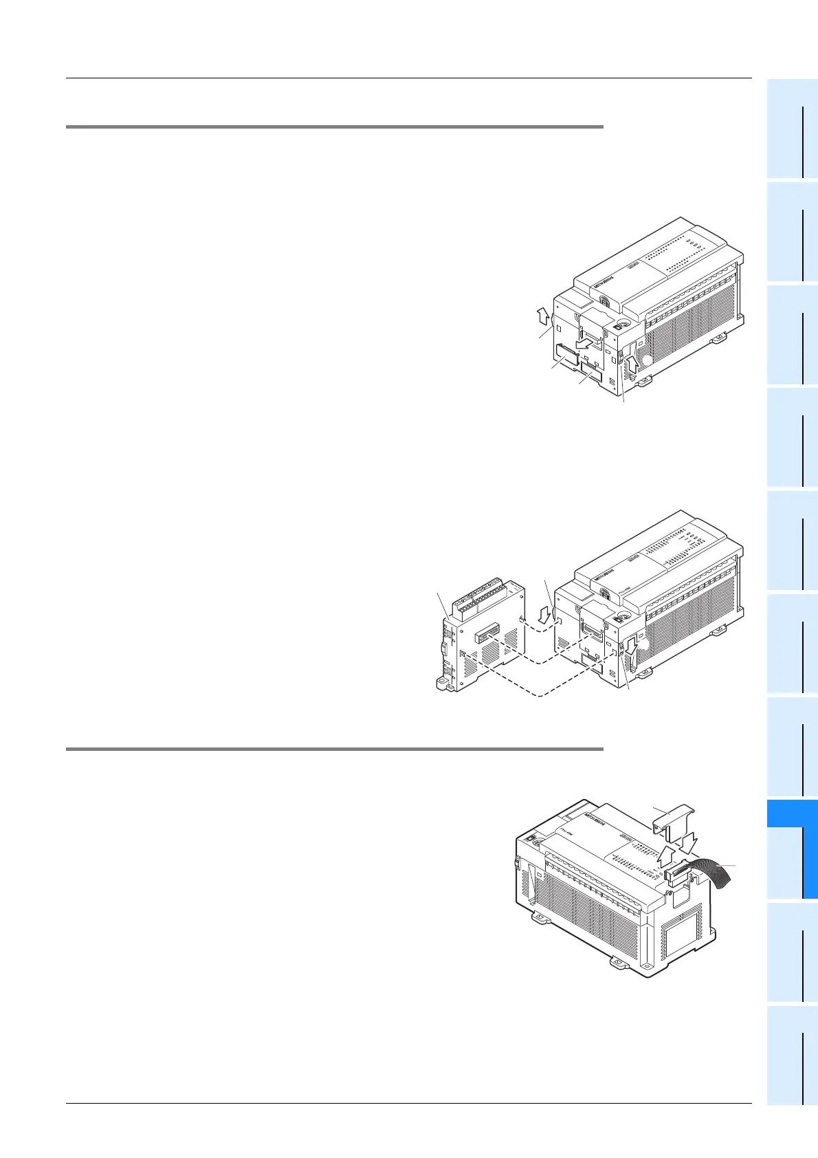
8.7.3 Connecting method B - connection of special adapter
When an expansion board is used, connect the board as stated in the previous subsection before connecting
the special adapter.
When a high-speed input/output special adapter is used, fit the adapter before connecting other special
adapters.
1 Remove the special adapter connector cover (A
in the right figure) from the expansion board.
• When fitting a high-speed input/output special adapter, also
remove the high-speed input/output special adapter connector
cover (C in the right figure).
• When adding a special adapter to the special adapter that has
been connected to the expansion board, read "expansion board"
as "special adapter."
2 Slide the special adapter connecting hooks (B in
the right figure) of the main unit.
• When adding a special adapter to the special adapter that has been connected to the main unit, read "main
unit" as "special adapter." (This applies to the following steps.)
3 Connect the special adapter (C in
the right figure) to the main unit as
shown in the right figure.
4 Slide the special adapter connecting
hooks (B in the right figure) of the
main unit to secure the special
adapter (C in the right figure).
8.7.4 Connecting method C - connection of powered extension unit/block to main unit
The procedures for connecting an powered extension unit/block to the main unit are explained below.
1 Remove the extension device connector cover
(A in the right figure) on the right side of the
main unit.
2 Connect the extension cable (B in the right fig-
ure) from the extension block to be connected
(right side) to the extension device connector
of the main unit.
• When connecting FX2N Series input/output powered extension
unit, FX
2N-10GM, FX2N-20GM, FX2N-1RM(-E)-SET or FX3U-
1PSU-5V, connect the unit to be added (right side) and the
existing unit (main unit) with the supplied extension cable.
3 Fit the extension device connector cover (A in the right figure).
RUN
STOP
FX
3U
-48MR/ES
FX
3U
-48M
ERROR
RUN
BATT
POWER
0
3
1
2
IN
6
4
5
21
7
20
24
22
23
26
25
10
11
13
12
16
14
15 17
27
OUT
03
1
2
64
5
21
7
20
24
22
23
26
25
10
11
1312
16
14
15
17
27
FX
3U
-48M
2
2
B
A
B
1
C
C
B
3
3
3
4
4
B
A
3
1
B

 Loading...


