FX3U Series Programmable Controllers
User’s Manual - Hardware Edition
178
10 Input Wiring Procedures (Input Interruption and Pulse Catch)
10.3 100V AC Input (Except Main Unit)
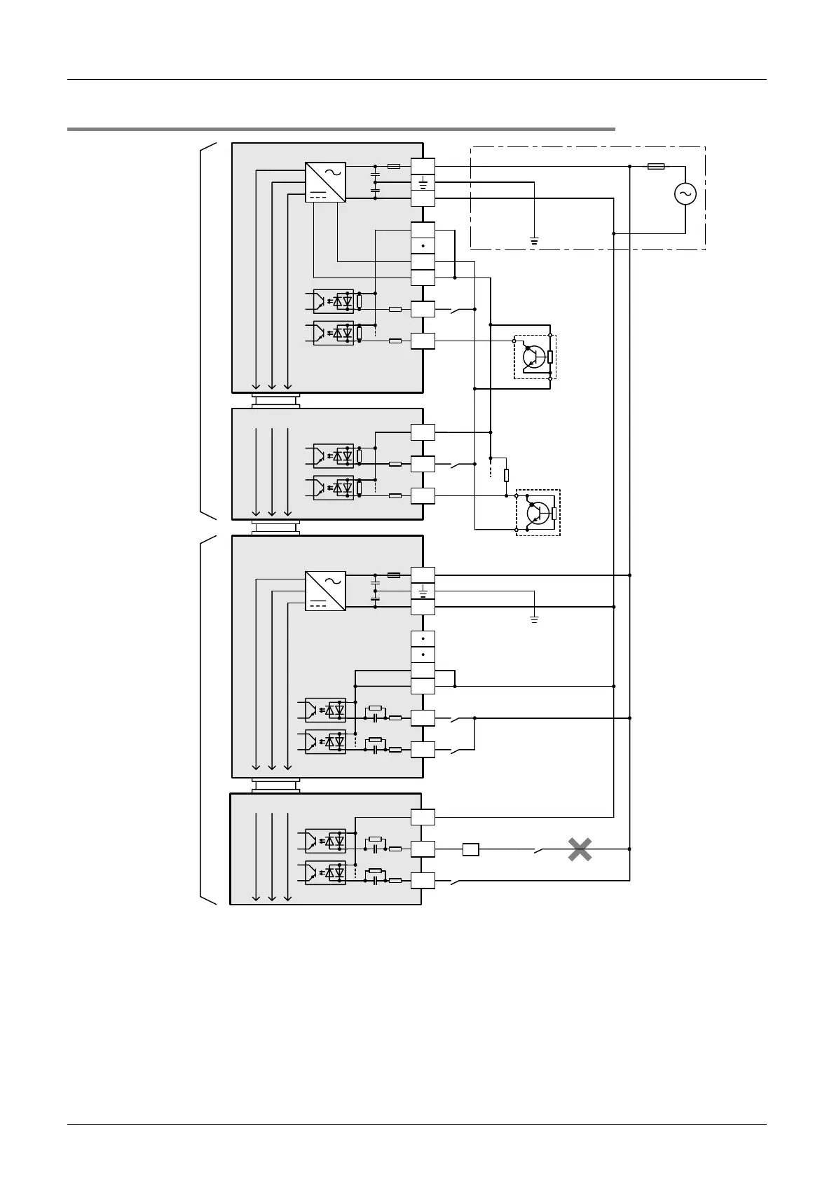
10.3.3 Example of external wiring
*1 Handle the power supply circuit correctly in
accordance with Chapter 9 "Preparation for
Wiring and Power Supply Wiring Procedures."
*2 For an input device having a parallel resistance
or a two-wire proximity switch, a bleeder
resistance may be required.
24V DC
input type
(Sink wiring)
X000
S/S
0V
24V
Main unit
N
L
X001
X0
S/S
X1
Input extension block
X0
Input / output powered extension unit
FX
2N
-48ER-UA1/UL
N
L
X1
5V 0V 24V
5V 0V 24V
Fuse
5V 0V 24V
Class D
grounding
Input
impedance
Input
terminal
Input
terminal
Input
terminal
*1
*2
24V0V
Two-wire
proximity
sensor
COM
COM
Class D
grounding
100V AC
input type
Three-
wire
sensor
X0
COM
X1
Input extension block
5V 0V 24V
MC
*3
*3 Do not take input signals from loads generating
surge.

 Loading...


