FX3U Series Programmable Controllers
User’s Manual - Hardware Edition
221
12 Output Wiring Procedures
12.4 External Wiring for Triac (SSR) Output Type
11
High-Speed
Counters
12
Output Wiring
13
Wiring for
Various Uses
14
Test Run,
Maintenance,
Troubleshooting
15
IInput/Output
Powered
Extension Units
16
Input/Output
Extension
Blocks
17
Extension
Power Supply
Unit
18
Other Extension
Units and
Options
19
Display Module
20
Terminal Block
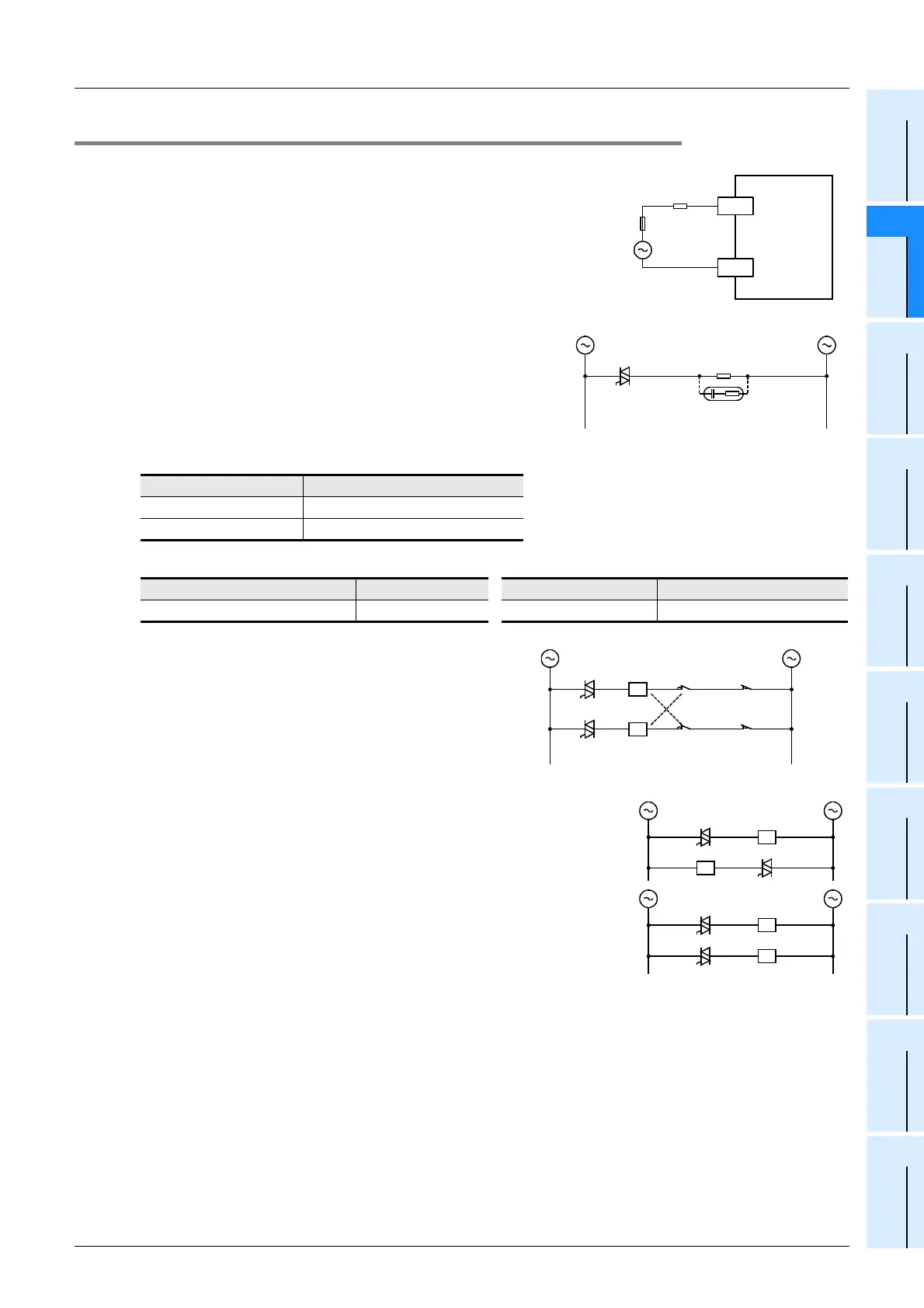
12.4.2 External wiring precautions
1. Protection circuit for load short-circuits
A short-circuit at a load connected to an output terminal could
cause burnout at the output element or the PCB. To prevent
this, a protection fuse should be inserted at the output.
2. Micro current load
The PLC’s internal Triac output circuit is equipped with a turn-
off C-R absorber. When connecting a very low current load of
"0.4VA/100V AC or less, or 1.6VA/200V AC or less", please
connect a surge absorber parallel to the load.
Select the rated voltage of a surge absorber that is suitable for
the load being used. Refer to the table below for other
specifications.
Reference
3. Interlock
For loads such as forward/reverse contactors, etc., where a
hazardous condition could result if switched ON
simultaneously, an external interlock should be provided for
interlocking the PLC’s internal programs as shown to the
right.
4. In-phase
PLC output contacts (*) should be used in an "in-phase"
manner.
Item Standard
Static electricity capacity Approx. 0.1µF
Resistance value Approx. 100 to 200Ω
Manufacturer Model name Manufacturer Model name
Okaya Electric Industries Co., Ltd. CR-10201 Rubycon Corporation 250MCRA104100M B0325
PLC
COM1
Load
Fuse
Y
Micro current load
Surge
absorber
Inter-
lock
Normal
rotation
Reverse
rotation
Limit of normal
rotation
PLC output
element
Limit of reverse
rotation
Bad
*
*
*
*
Good

 Loading...


