208
FX3U Series Programmable Controllers
User’s Manual - Hardware Edition
12 Output Wiring Procedures
12.2 External Wiring for Relay Output
12.2 External Wiring for Relay Output
This section explains the relay output specifications (main unit) and external wiring.
• For the main unit, refer to Subsection 12.2.1 "Output specifications (main unit)", Subsection 12.2.3
"Handling of relay output", Subsection 12.2.4 "External wiring precautions" and Subsection 12.2.5
"Example of external wiring" in this section.
• For the input/output powered extension units/blocks, refer to Subsection 12.2.3 "Handling of relay output"
and Subsection 12.2.4 "External wiring precautions" in this section. For their specifications and examples
of wiring, refer to the specification for each model.
→ For the specifications on the input/output powered extension unit, refer to Chapter 15.
→ For the specifications on the input/output extension block, refer to Chapter 16.
12.2.1 Output specifications (main unit)
Number of output points per common terminal
•On FX
3U-16MR/S, one common terminal is used for one output point.
• On models other than FX
3U-16MR/S, one common terminal is used for four or eight output points.
Item
Relay output specifications
FX
3U
-16MR/
S
FX
3U
-32MR/
S
FX
3U
-48MR/
S
FX
3U
-64MR/
S
FX
3U
-80MR/
S
FX
3U
-128MR/
ES
Number of output
points
8 points 16 points 24 points 32 points 40 points 64 points
Output connecting
type
Fixed terminal
block
(M3 screw)
Removable terminal block (M3 screw)
Output form Relay
External power
supply
30V DC or less or 240V AC or less
(250V AC or less when the unit does not comply with CE, UL or cUL standards)
Max. load
Resistance
load
2 A/point
The total load current of resistance loads per common terminal should be the following
value.
→ For details on the common terminal for each model,
refer to the terminal block layout.
• 1 output point/common terminal: 2 A or less
• 4 output points/common terminal: 8 A or less
• 8 output points/common terminal: 8 A or less
Inductive
load
80 VA
→ For the product life, refer to Subsection 12.2.2.
→ For cautions on external wiring, refer to Subsection 12.2.4.
Min. load 5V DC, 2mA (reference value)
Open circuit leakage
current
−
Response
time
OFFON Approx. 10ms
ONOFF Approx. 10ms
Circuit insulation Mechanical insulation
Display of output
operation
LED on panel lights when power is applied to relay coil.
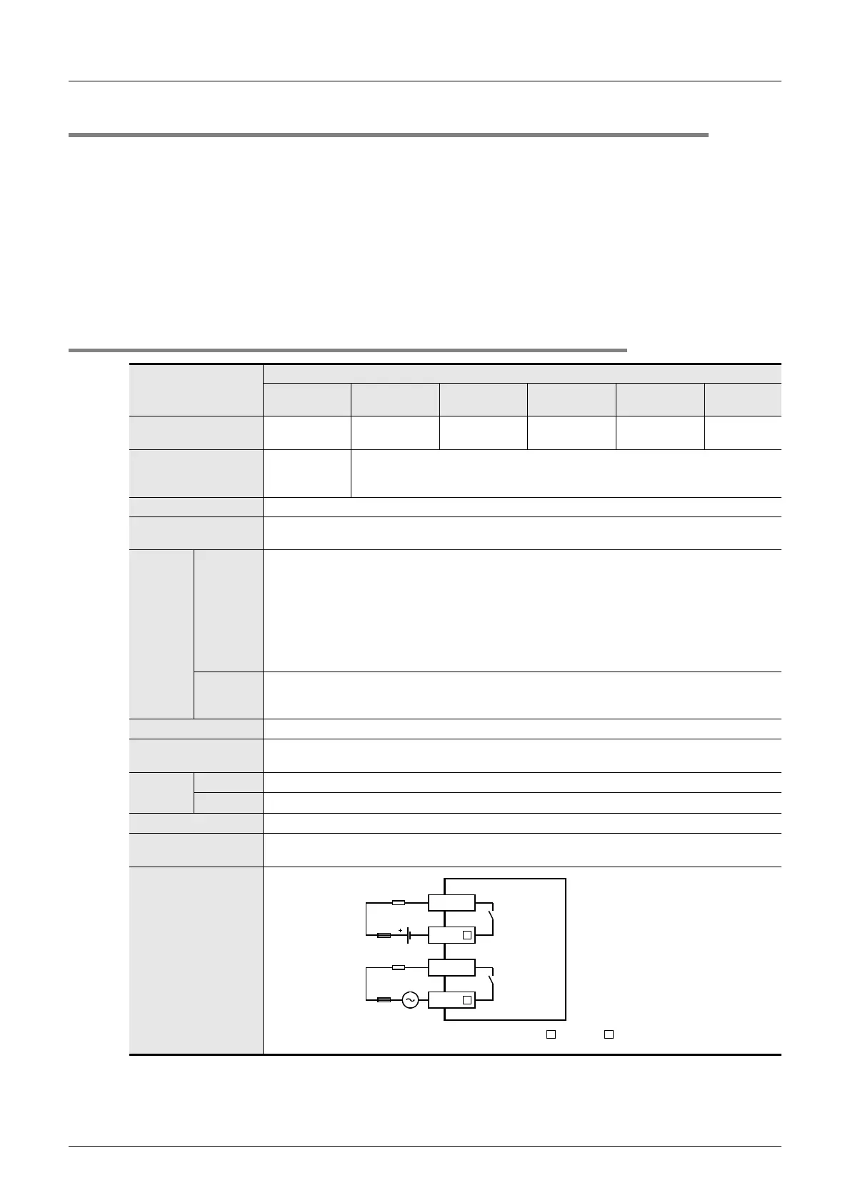
Output circuit
configuration
External
power supply
Load
Fuse
Y
COM
DC power
supply
Fuse
Y
COM
A common number applies to the of [COM ].
Load

 Loading...


