FX3U Series Programmable Controllers
User’s Manual - Hardware Edition
238
13 Examples of Wiring for Various Uses
13.6 Seven Segment with Latch [SEGL Instructions (FNC74)/BCD Instructions (FNC18)]
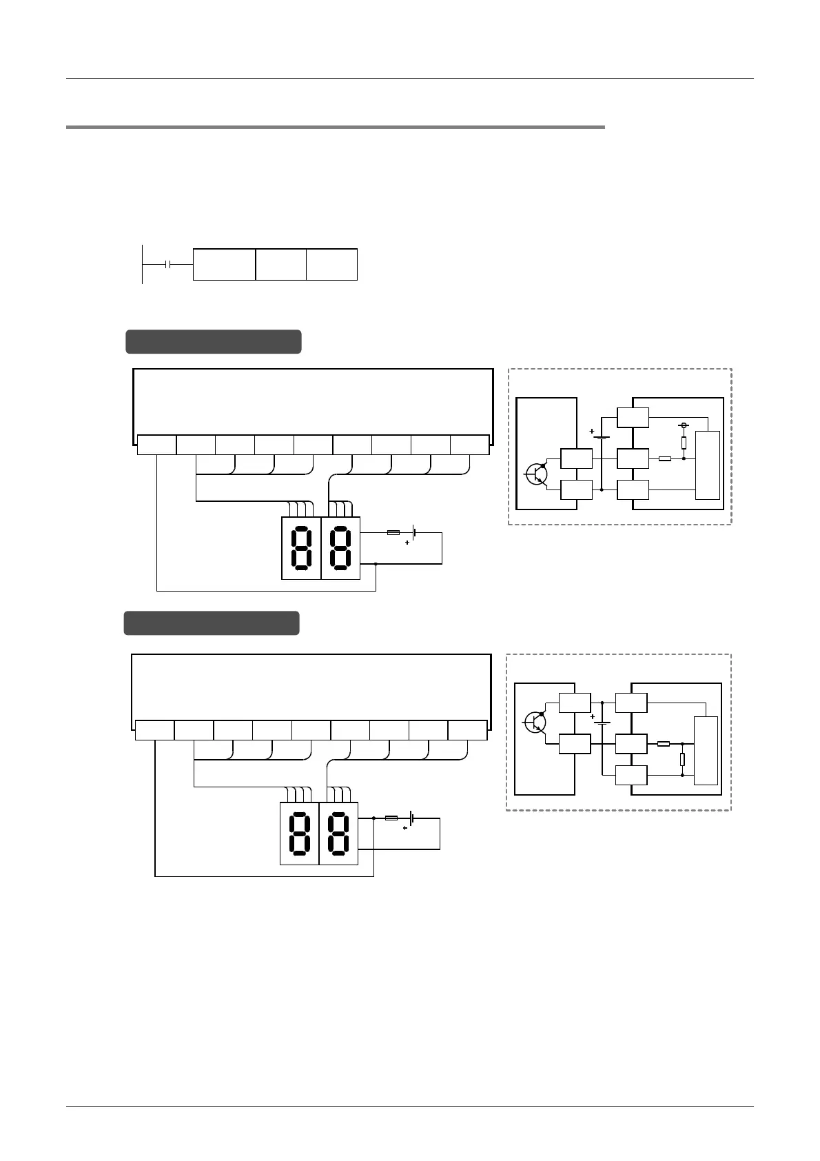
13.6.2 When BCD instructions are used
This subsection gives examples of wiring for displaying the current value of D100 on the 2-digit 7-segment
display.
1. Main Unit
Example of program
Example of wiring
M8000
D100 K2Y010BCD
Y010COM3 Y011 Y012 Y013 Y014 Y015 Y016 Y017
12481248
8421 8421
Transistor output (sink)
Main unit (Ex: FX
3U
-32MT/ES)
Signal
-
7-segment display
+
Y
COM1
PLC
7-segment display to be used for sink
wiring (in the case of transistor output)
In the case of sink wiring
Y010+V2 Y011 Y012 Y013 Y014 Y015 Y016 Y017
12481248
8421 8421
Transistor output (source)
Signal
-
7-segment display
+
Y
PLC
+V0
7-segment display to be used for source
wiring (in the case of transistor output)
Main unit (Ex: FX
3U
-32MT/ESS)
In the case of source wiring

 Loading...


