FX3U Series Programmable Controllers
User’s Manual - Hardware Edition
140
8 Installation In Enclosure
8.6 Procedures for Installing Directly (with M4 Screws)
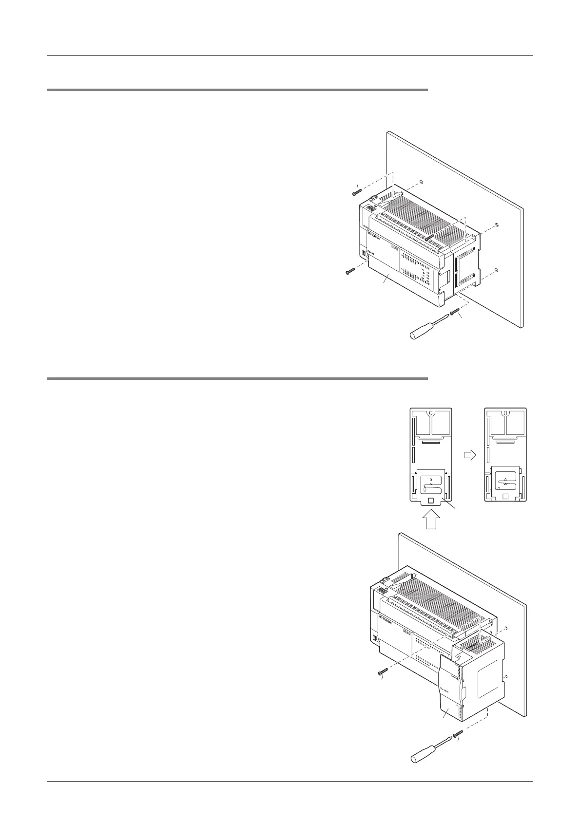
8.6.3 Installation of main unit
Mount the expansion board and special adapters on the main unit before installing the unit in the enclosure.
→ For the connection procedure, refer to Subsection 8.7.2, 8.7.3, and 9.5.2.
1 Make mounting holes in the mounting sur-
face according to the external dimensions
diagram.
2 Fit the main unit (A in the right figure)
based on the holes, and secure it with M4
screws (B in the right figure).
The positions and number of screws depend on the
product. Refer to the external dimensions diagram.
→ For the external dimensions, refer to Section 4.6.
8.6.4 Installation of input/output powered extension unit/block and special function unit/
block
1 Make mounting holes in the mounting sur-
face according to the external dimensions
diagram
2 Push in the DIN rail mounting hook (A in
the right figure) of the input/output exten-
sion block.
If the DIN rail mounting hook is not pushed in, the
screw hole is covered, and the block cannot be
mounted.
For input/output powered extension units, 8-point type
input/output extension blocks and special extension
units/blocks, this operation is unnecessary.
3 Fit the input/output extension block (B in
the right figure) based on the holes, and
secure it with M4 screws (C in the right fig-
ure).
The positions and number of screws depend on the
product. Refer to the external dimensions diagram.
→ For the external dimensions of the input/output
powered extension unit, refer to Chapter 15.
→ For the external dimensions of the input/output
extension block, see Chapter 16.
→ For the external dimensions of the special function
units/blocks, see Chapter 18.
B
B
A
Rear panel
A
2
Rear panel
FX
3U
-48MFX
3U
RUN
POWER
ERROR
BATT
FX
3U
-48MFX
3U
ERROR
RUN
BATT
POWER
03
1
2
IN
OUT
6
4
5
21
7
20
2422
23
26
25
10
11
13
12 16
14
15
17
27
0
3
1
2
6
4
5
21
7
20
2422
23 2625
10
11 13
12
16
14
15
17
27
B
C
C

 Loading...


