FX3U Series Programmable Controllers
User’s Manual - Hardware Edition
209
12 Output Wiring Procedures
12.2 External Wiring for Relay Output
11
High-Speed
Counters
12
Output Wiring
13
Wiring for
Various Uses
14
Test Run,
Maintenance,
Troubleshooting
15
IInput/Output
Powered
Extension Units
16
Input/Output
Extension
Blocks
17
Extension
Power Supply
Unit
18
Other Extension
Units and
Options
19
Display Module
20
Terminal Block
12.2.2 Product life of relay contacts
→ For product life of relay contacts, refer to Subsection 4.4.2.
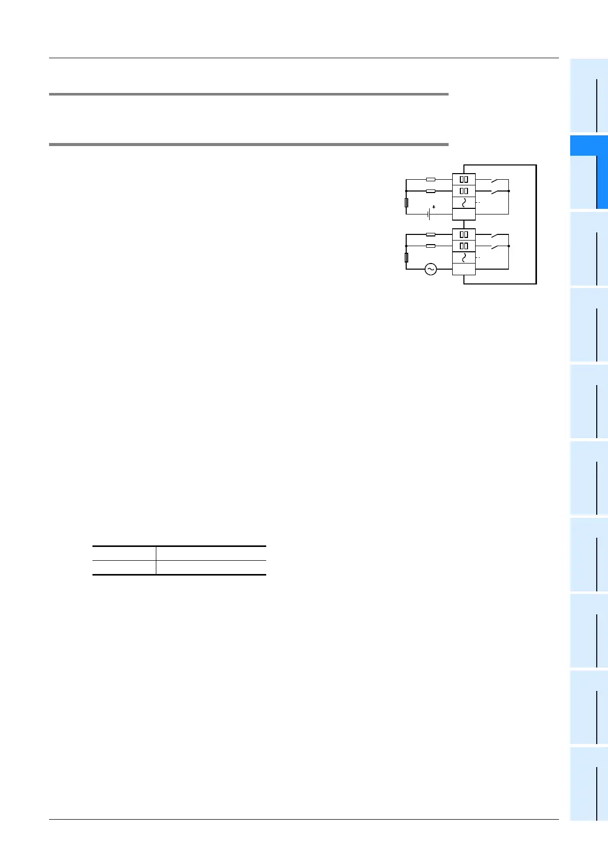
12.2.3 Handling of relay output
1. Output terminal
One common terminal is used for 1, 4 or 8 relay output points.
The common terminal blocks can drive loads of different circuit
voltage systems (for example, 200V AC, 100V AC and 24V
DC).
2. External power supply
Use an external power supply of 30V DC or less or 240V AC or less (250V AC or less when the unit does not
comply with CE, UL or cUL standards) for loads.
3. Circuit insulation
The PLC internal circuit and external load circuits are electrically insulated between the output relay coil and
contact. The common terminal blocks are separated from one another.
4. Display of operation
When power is applied to the output relay coil, the LED is lit, and the output contact is turned on.
5. Response time
The response time of the output relay from when the power is applied to the coil until the output contact is
turned on and from when the coil is shut off until the output contact is turned off is approx. 10ms.
6. Output current
At a circuit voltage of 240V AC or less (250V AC or less when the unit does not comply with CE, UL or cUL
standards), a resistance load of 2A per point or an inductive load of 80VA or less (100V AC or 200V AC) can
be driven.
→ For the life of the contact for switching an inductive load, refer to Subsection 12.2.2.
When an inductive load is switched, connect a diode (for commutation) or a surge absorber in parallel with
this load.
7. Open circuit leakage current
When the output contact is turned off, no current leaks.
DC circuit Diode (for commutation)
AC circuit Surge absorber
PLC
Load
24V DCFuse
Y 0
Y 1
COM1
Load
100V ACFuse
Y 4
Y 5
COM2

 Loading...


