FX3U Series Programmable Controllers
User’s Manual - Hardware Edition
166
10 Input Wiring Procedures (Input Interruption and Pulse Catch)
10.1 Before Starting Input Wiring
10.1 Before Starting Input Wiring
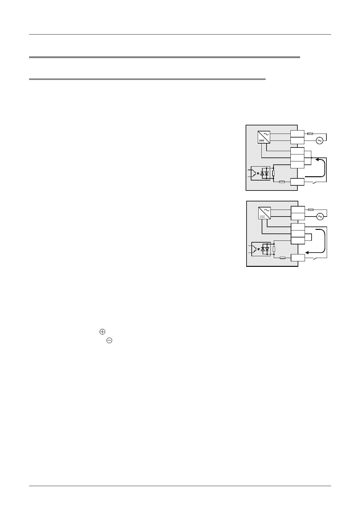
10.1.1 Sink and source input (24V DC input type)
The input terminals (X) of the main unit are common to sink/source input of 24V DC internal power.
FX
2N Series input/output powered extension units/blocks have input terminals common to sink/source input
or only for sink input.
1. Difference between circuits
• Sink input [-common]
Sink input means a DC input signal with current-flow from the input
(X) terminal.
When a sensor with a transistor output is connected, NPN open
collector transistor output can be used.
• Source input [+common]
Source input means a DC input signal with current-flow into the input
(X) terminal.
When a sensor with a transistor output is connected, PNP open
collector transistor output can be used.
2. Method of switching between sink/source input
To switch the input type to sink or source input, wire the S/S terminal to the 0V or 24V (+ or −) terminal.
1) In the case of AC power supply type
- Sink input: [24V] terminal and [S/S] terminal are connected.
- Source input: [0V] terminal and [S/S] terminal are connected.
→ Refer to Subsection 10.2.4 and 10.2.5 for wiring examples.
2) In the case of DC power supply type
- Sink input: [ ] terminal and [S/S] terminal are connected.
- Source input: [ ] terminal and [S/S] terminal are connected.
→ Refer to Subsection 10.2.6 and 10.2.7 for wiring examples.
3. Instructions for using
• Concurrent use of sink/source input
It is possible to set all input terminals (X) of the main unit to the sink input mode or the source input mode.
However, sink and source input terminals cannot be used concurrently.
- The main unit and input/output powered extension units are individually set to the sink or source input mode.
- The input mode of an input/output extension block is determined according to the selection of the sink or
source input mode on the powered extension unit (power source).
• Caution in selecting model
A type common to sink/source input and a type only for sink input are both available. Select a proper type.
Differences from FX
2N PLCs in input specifications (reference)
FX
2N PLCs only for sink input (manuals in Japanese are supplied) and those common to sink/source input
(manuals in English are supplied) have different model names.
•In FX
2N
PLCs only for sink input, the S/S terminal and the 24V terminal are connected unlike in FX
3U
PLCs.
•FX2N PLCs common to sink/source input are switched to the sink or source input mode by external wiring
like FX
3U PLCs.
24V
N
L
X
S/S
0V
24V
N
L
X
S/S
0V

 Loading...


