267
FX3U Series Programmable Controllers
User’s Manual - Hardware Edition
15 FX2N-32/48E*-* (Input/Output Powered Extension Units)
15.2 Power Supply Specifications (Power Supply Input/24V DC Service Power Supply)
11
High-Speed
Counters
12
Output Wiring
13
Wiring for
Various Uses
14
Test Run,
Maintenance,
Troubleshooting
15
IInput/Output
Powered
Extension Units
16
Input/Output
Extension
Blocks
17
Extension
Power Supply
Unit
18
Other Extension
Units and
Options
19
Display Module
20
Terminal Block
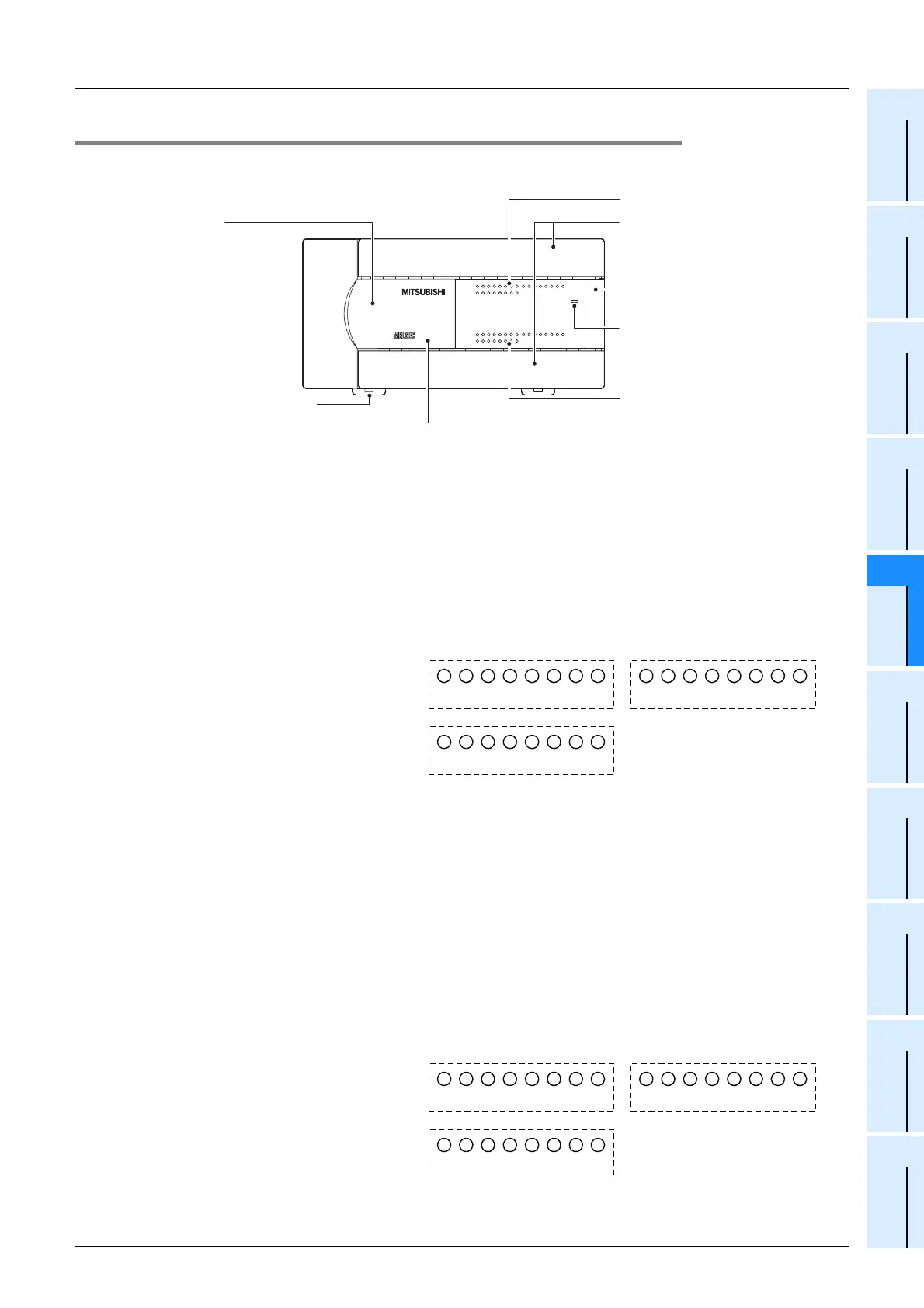
15.2.2 Part names
1. Front
[1]
Top cover When adding this to the main unit, connect the supplied extension cable or
the optional extension cable to the connector under this top cover.
[2]
DIN rail mounting hooks
(2 places)
The input/output powered extension unit can be installed on DIN rail
(35 mm (1.38") wide).
[3]
Model name (abbreviation)
The model name of the input/output powered extension unit is indicated.
[4]
Input display LEDs (red) When an input terminal (X0, X1, etc.) is turned on, the corresponding LED
lamps are also turned on.
The input numbers change depending on input/output allocation.
The input/output powered extension unit (48 points type) assigns input
numbers in ascending order from A→B→C below.
[5]
Terminal block covers The covers can be opened about 90° for wiring.
Keep the covers closed while the PLC is running (the unit power is on).
[6]
Extension device connecting
connector cover
Connect the extension cable of input/output powered extension unit/block
or special function unit/block to the extension device connecting connector
under this cover.
FX
3U Series extension devices, FX2N Series extension devices and FX0N
Series special function devices are compatible and can be connected.
→ For details on extension devices, refer to Chapter 15,
Chapter 16 and Section 18.1.
[7]
POWER LED (green)
The LED lamp is on (green) while the power supply terminal is on.
[8]
Output display LEDs (red) When an output terminal (Y0, Y1, etc.) is turned on, the corresponding
LED lamps are also turned on. The output numbers change depending on
input/output allocation.
The input/output powered extension unit (48 points type) assigns output
numbers in ascending order from A→B→C below.
FX
2N
-48ER
72 456
1
3
0
72 456
1
3
0
OUT
IN
L
X5 X7
X1
X3 X5 X7
X1
X3 X5 X7
X4 X6
X0
X2 X4 X6
X0
X2 X4 X6
24V
N
0VS/S
X0
X1
X2
X3
COM4
Y4
Y5
COM5
Y7COM2
Y4
Y5
Y6
Y7 COM3
Y0
Y1
Y2
Y3
COM1
Y0
Y1
Y2
Y3
Y4
Y5
Y6
Y7
Y0
Y1
Y2
Y3
Y6
POWER
72 456
1
3
0
72 456
1
3
0
72456
1
3
0
72456
1
3
0
[1] Top cover
[2] DIN rail mounting hooks
[3] Model name
[8] Output display LEDs
[7] POWER LED
[6] Extension device connecting
connector cover
[5] Terminal block covers
[4] Input display LEDs
A
0 1 2 3 4 5 6 7 0 1 2 3 4 5 6 7
C
B
0 1 2 3 4 5 6 7
A
0 1 2 3 4 5 6 7 0 1 2 3 4 5 6 7
C
B
0 1 2 3 4 5 6 7

 Loading...


