FX3U Series Programmable Controllers
User’s Manual - Hardware Edition
145
8 Installation In Enclosure
8.7 Connecting Methods for Main Unit and Extension Devices
1
Introduction
2
Features and
Part Names
3
Product
Introduction
4
Specifications
5
Version and
Peripheral
Devices
6
System
Configuration
7
Input/Output
Nos., Unit Nos.
8
Installation
9
Preparation and
Power Supply
Wiring
10
Input Wiring
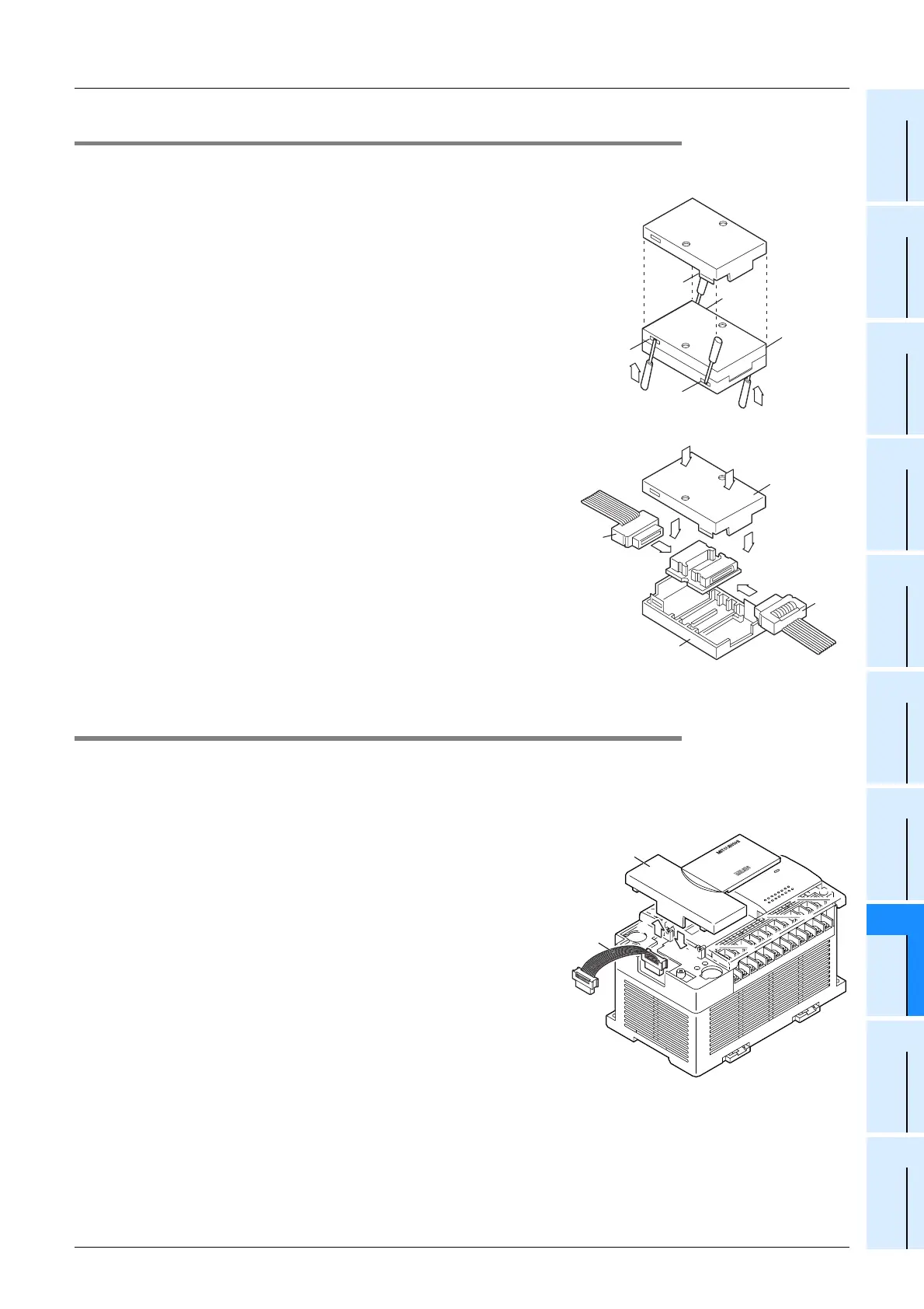
8.7.6 Connecting method E - connection of extension cable and FX2N-CNV-BC
This subsection explains the procedures for connecting an extension cable and FX2N-CNV-BC to the
extension cable of the powered extension unit/block.
1 Separate the case of FX2N-CNV-BC into two
pairs as shown right.
To separate the case, use a precision flathead screw-
driver.
Slightly insert the tip of the screwdriver into the part A
shown in the right figure, and the hook (B in the right fig-
ure) will come off (4 places).
2 Connect the extension cable on the upstream
side (C in the right figure).
3 Connect the extension cable on the down-
stream side (D in the right figure).
4 Fit the upper cover (E in the right figure) and
the lower cover (F in the right figure), and
press down the upper cover until it is
hooked.
8.7.7 Connecting method F - connection of input/output powered extension unit
This subsection explains the procedures for connecting an input/output powered extension unit.
1 Remove the top cover (A in the right figure)
on the left side of the input/output powered
extension unit.
2 Connect the connector of the extension cable
(supplied) (B in the right figure) to the exten-
sion connector.
3 Connect the connector of the extension cable
(supplied) (B in the right figure) to the exten-
sion connector of the unit to be added (right
side).
4 Fit the top cover (A in the right figure).
A
A
A
A
B
1
1
4
4
E
2
3
D
C
FX
0N
-30EC
FX
0N
-65EC
F
FX
2N
-32ET
A
B
1
4

 Loading...


