212
FX3U Series Programmable Controllers
User’s Manual - Hardware Edition
12 Output Wiring Procedures
12.3 External Wiring of Transistor Output (Sink/Source) Type
12.3 External Wiring of Transistor Output (Sink/Source) Type
This section explains the handling and external wiring of transistor output.
• For the main unit, refer to Subsection 12.3.1 "Output specifications (main unit) transistor output (sink
type)", Subsection 12.3.2 "Output specifications (main unit) transistor output (source type)", Subsection
12.3.3 "Handling of transistor output", Subsection 12.3.4 "External wiring precautions" and Subsection
12.3.5 "Example of external wiring".
• For the input/output powered extension units/blocks, refer to Subsection 12.3.3 "Handling of transistor
output" and Subsection 12.3.4 "External wiring precautions" in this section. For the specifications and
examples of wiring, refer to the specifications for each model.
→ For the specifications on the input/output powered extension units, refer to Chapter 15.
→ For the specifications on the input/output extension blocks, refer to Chapter 16.
12.3.1 Output specifications (main unit) transistor output (sink type)
Number of output points per common terminal
•On FX
3U-16MT/S, one common terminal is used for 1 output point.
• On models other than FX
3U-16MT/S, 1 common terminal is used for 4 or 8 output points.
Item
Transistor output (sink) specifications
FX
3U
-16MT/
S
FX
3U
-32MT/
S
FX
3U
-48MT/
S
FX
3U
-64MT/
S
FX
3U
-80MT/
S
FX
3U
-128MT/
ES
Number of output
points
8 points 16 points 24 points 32 points 40 points 64 points
Connecting type
Fixed terminal
block
(M3 screw)
Removable terminal block (M3 screw)
Output type/form Transistor/sink output
External power
supply
5 to 30V DC
Max.
load
Resistance
load
0.5A / point
The total load current of resistance loads per common terminal should be the following value.
→ For details on the common terminal for each model,
refer to the terminal block layout.
• 1 output point/common terminal: 0.5 A or less
• 4 output points/common terminal: 0.8 A or less
• 8 output points/common terminal: 1.6 A or less
Inductive
load
12W/24V DC
Open circuit leakage
current
0.1 mA or less/30V DC
ON voltage 1.5 V or less
Min. load −
Response
time
OFF→ON
Y000 to Y002:5 µs or less/10 mA or more (5 to 24V DC)
Y003 or more:0.2 ms or less/200 mA or more (at 24V DC)
ON→OFF
Y000 to Y002:5 µs or less/10 mA or more (5 to 24V DC)
Y003 or more:0.2 ms or less/200 mA or more (at 24V DC)
Circuit insulation Photocoupler insulation
Display of output
operation
LED on panel lights when photocoupler is driven.
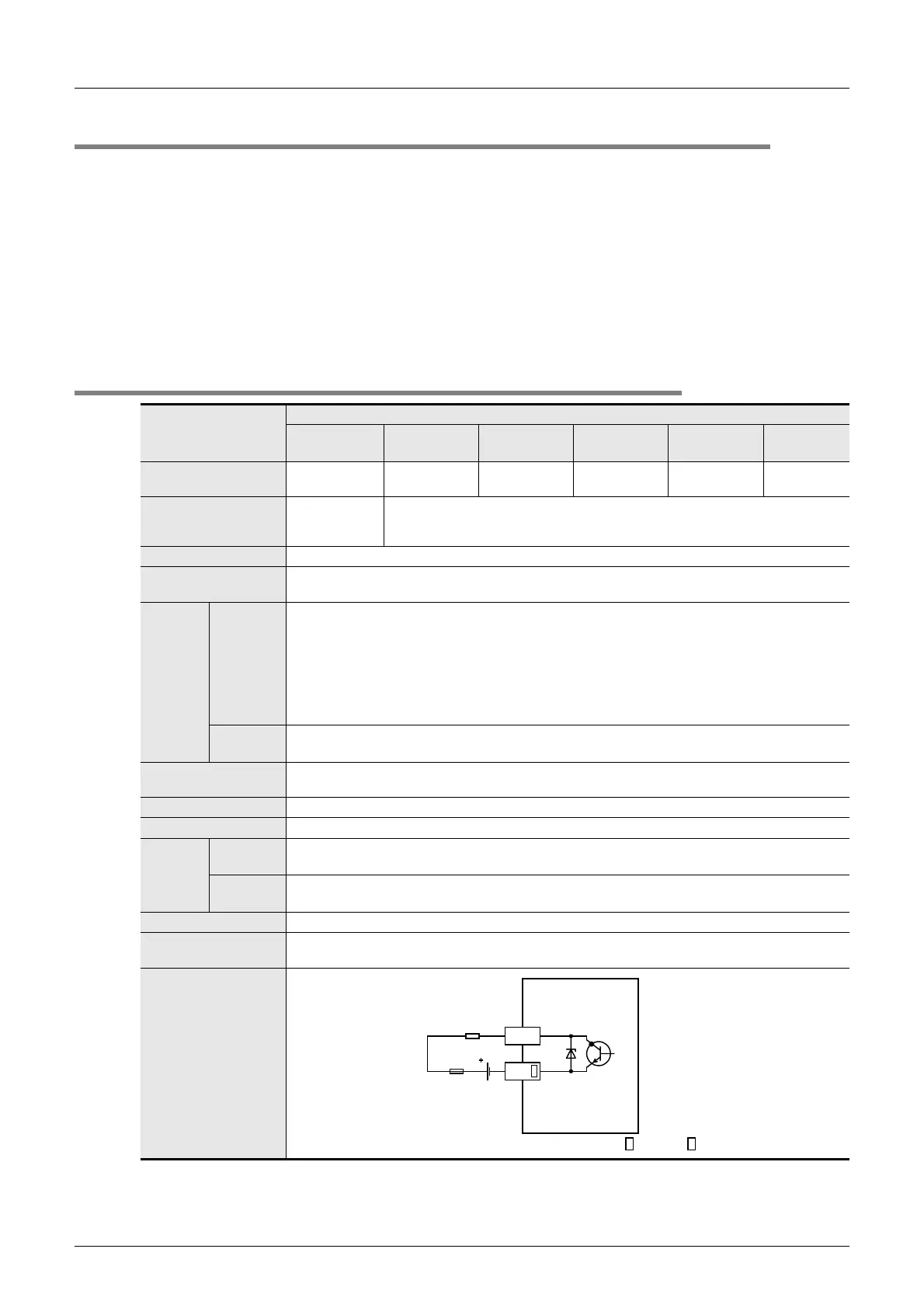
Output circuit
configuration
Load
Fuse
DC power
supply
Y
COM
A common number applies to the of [COM ].

 Loading...


