FX3U Series Programmable Controllers
User’s Manual - Hardware Edition
199
11 Use of High-speed Counters (C235 to C255)
11.10 Examples of External Wiring (Rotary Encoder)
11
High-Speed
Counters
12
Output Wiring
13
Wiring for
Various Uses
14
Test Run,
Maintenance,
Troubleshooting
15
IInput/Output
Powered
Extension Units
16
Input/Output
Extension
Blocks
17
Extension
Power Supply
Unit
18
Other Extension
Units and
Options
19
Display Module
20
Terminal Block
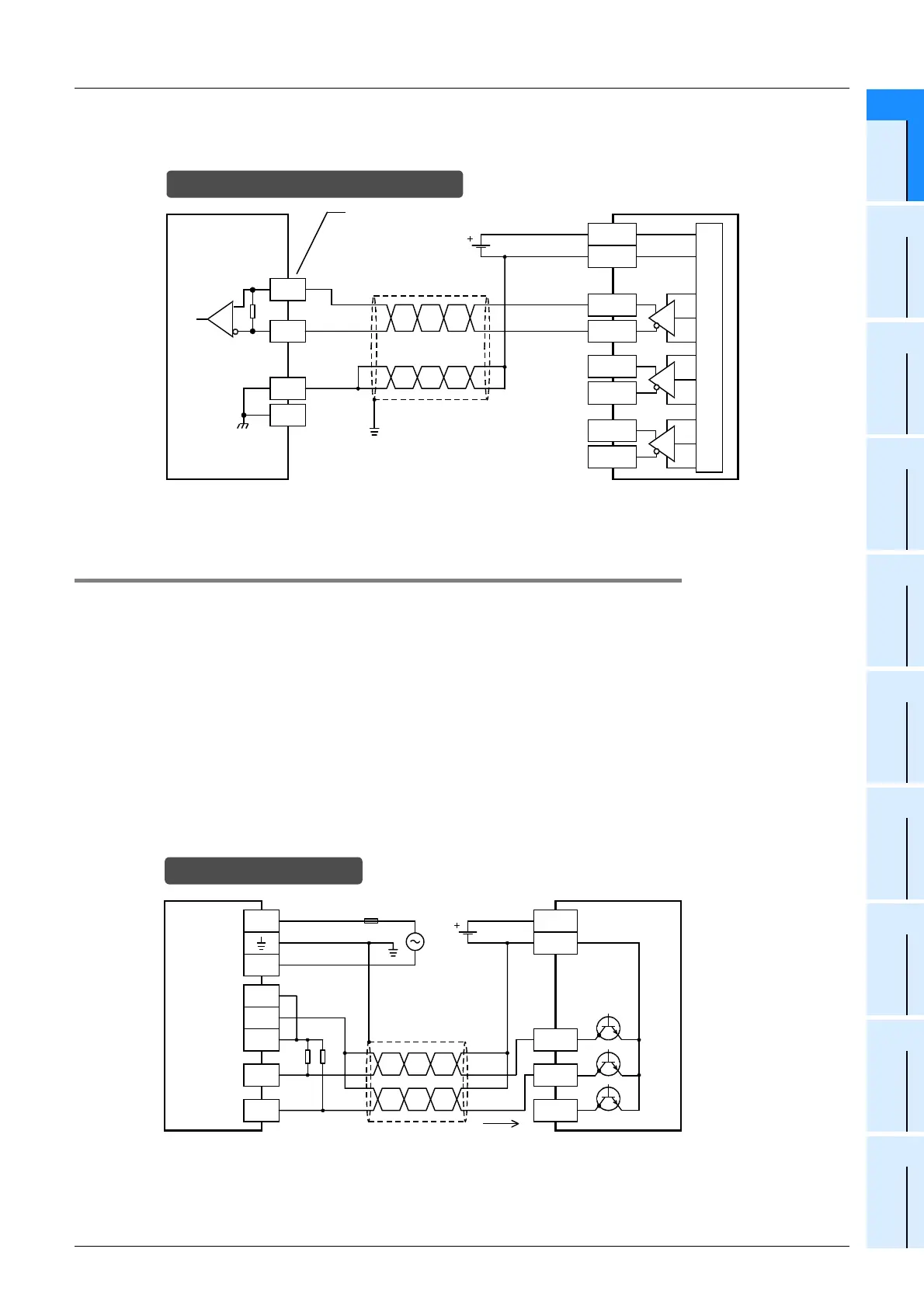
2. When high-speed input special adapter (FX3U-4HSX-ADP) is used
1) Differential line driver output rotary encoder
11.10.2 2-phase 2-input [C251 to C255]
The following examples of wiring apply to the cases where C251 is used. When another high-speed counter
number is used, wire the counter referring to the following diagrams.
1. When the input terminals of the main unit are used
When pulses having a response frequency of 50 k to 100 kHz are captured to the high-speed counter using
the input terminals X000 to X005, wire the counter as stated below.
• The wiring length should be 5m (16’4") or less.
• For connecting cables, use shielded twisted-pair cables. Ground the shield of each shielded cable only on
the PLC side.
• Connect a bleeder resistance of 1.5kΩ (1W or more) to the input terminal, so that the sum of the load
current of the open collector transistor output on the mating device side and the input current of the main
unit is 20mA or more.
1) NPN open collector transistor output rotary encoder
In the case of differential line driver wiring
* The grounding resistance should be 100
Ω
or less.
High-speed input
special adapter
X0/3-
SG
X000
X0/3+
Class D
grounding*
X000
Equivalent to
AM26C32
330
Ω
Twisted-pair
shielded wire
SG
Phase A-
-
+
Rotary encoder
Phase B+
Phase Z+
Phase A+
Phase B-
Phase Z-
Non-inverted
output
Inverted
output
Input No. of first/second
unit
* The grounding resistance should be 100
Ω
or less.
PLC
S/S
L
N
24V
0V
24V
Rotary encoder
Class D
grounding*
Fuse
24V DC
In the case of sink wiring
0V
X000
X001
1.5k
Ω
Phase A
Phase B
Phase Z
20mA or
more

 Loading...


