FX3U Series Programmable Controllers
User’s Manual - Hardware Edition
425
20 FX-16/32E*-*-TB (Terminal Block)
20.8 FX-16EYT-TB, FX-16EYT-H-TB
11
High-Speed
Counters
12
Output Wiring
13
Wiring for
Various Uses
14
Test Run,
Maintenance,
Troubleshooting
15
IInput/Output
Powered
Extension Units
16
Input/Output
Extension
Blocks
17
Extension
Power Supply
Unit
18
Other Extension
Units and
Options
19
Display Module
20
Terminal Block
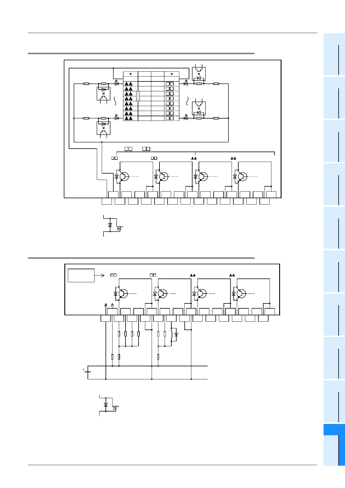
20.8.2 Internal circuit
20.8.3 Example of output external wiring
1 3
4
5
60 2
7 1 3
0 2 4
5
6
724+
24-
COM1
COM1
COM2
COM2
COM3
COM3
COM4
COM4
(20)
COM
6
7
5
4
3
2
1
0
COM
6
7
5
4
3
2
1
0
(10)
(19) (9)
(18) (8)
(17) (7)
(6)
(5)
(4)
(3)
(2)
(1)
(16)
(15)
(14)
(13)
(12)
(11)
0123 4567 0123 4567
Photo-
coupler
Photo-
coupler
3.3k
Ω
3.3k
Ω
Photo-
coupler
Photo-
coupler
* For the FX-16EYT-H-TB, the output transistor elements are as shown in the figure below.
* * * *
0 to 7 Lower numbers
0 to
7 Higher numbers
3.3k
Ω
3.3k
Ω
1 3
4
5
60 2
7 1 3
0 2 4
5
6
724+
24-
COM1
COM1
COM2
COM2
COM3
COM3
COM4
COM4
0123 4567 0123 4567
PLC output
No.
Photo-coupler
power supply
24V
DC
Fuse
* * * *
* For the FX-16EYT-H-TB, the output transistor elements are as shown in the figure below.
Fuse

 Loading...


