FX3U Series Programmable Controllers
User’s Manual - Hardware Edition
116
6 Examination of System Configuration
6.9 Example of System Configuration and System Modification
7 Determine whether the devices can be connected to the input/output pow-
ered extension unit.
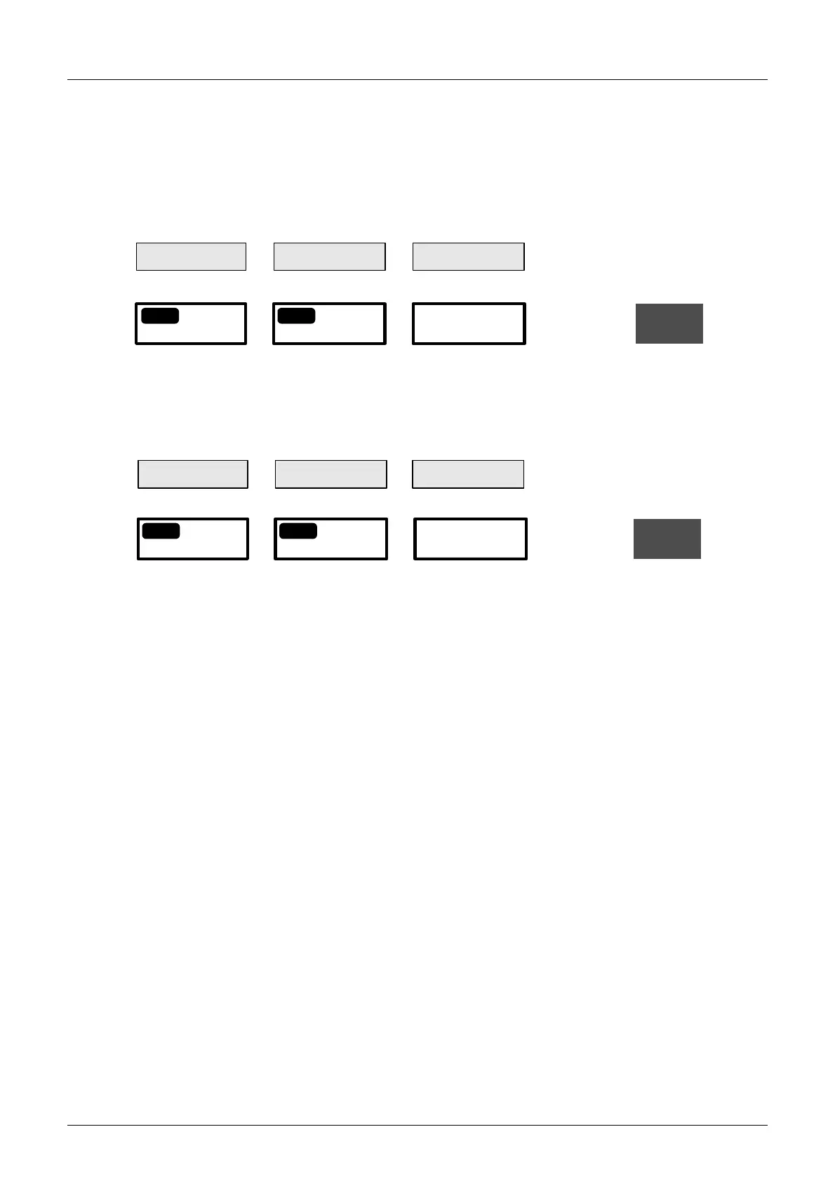
Calculate the current by the following formula to confirm whether the extension devices selected in
Step 4 can be connected.
1. Calculate the current consumption of the built-in 5V DC power supply.
2. Calculate the current consumption of the built-in 24V DC power supply (24V DC service
power supply).
The value obtained by this calculation (when the value is positive) indicates the remaining capacity of 24V DC
service power supply, and the capacity can be used for external loads
8 Verify the evaluation results.
Since the capacities of the 5V DC and 24V DC power supplies and the number of input/output
points are within the specified ranges, the reexamined system configuration is feasible.
390mA
-
690mA 300mA
=
OK
≥
0mA
Current consumption
Capacity of 5V DC
power supply
Calculation result
Input/output powered
extension unit
Total of current consumed by
extension devices
3-
2
4-
2
0mA
-
250mA 250mA
=
OK
≥
0mA
Current consumption
Capacity of 24V DC
power supply
Calculation result
Input/output powered
extension unit
Total of current consumed by
extension devices
3-
3
4-
3

 Loading...


