(2)
Safety Precautions
(Read these precautions before use.)
2. INSTALLATION PRECAUTIONS
Reference
• Make sure to cut off all phases of the power supply externally before attempting installation or
wiring work.
Failure to do so may cause electric shock.
123
407
Reference
•
Use the product within the generic environment specifications described in Section 4.1 of this manual.
Never use the product in areas with excessive dust, oily smoke, conductive dusts, corrosive gas
(salt air, Cl
2, H2S, SO2 or NO2), flammable gas, vibration or impacts, or exposed to high
temperature, condensation, or rain and wind.
If the product is used in such conditions, electric shock, fire, malfunctions, deterioration or damage
may occur.
• Do not touch the conductive parts of the product directly to avoid failure or malfunctions.
• Install the product securely using a DIN rail or mounting screws.
• Install the product on a flat surface.
If the mounting surface is rough, undue force will be applied to the PC board, thereby causing
nonconformities.
• Make sure to affix the function extension board with tapping screws.
Tightening torque: 0.3 to 0.6 N
•
m
Contact failures may cause malfunctions.
•
When drilling screw holes or wiring, make sure cutting or wire debris does not enter the ventilation slits.
Failure to do so may cause fire, equipment failures or malfunctions.
• Be sure to remove the dust proof sheet from the PLC's ventilation port when installation work is
completed.
• Failure to do so may cause fire, equipment failures or malfunctions.
• Connect the extension cables, peripheral device cables, input/output cables and battery
connecting cable securely to their designated connectors.
Unsecured connection may cause malfunctions.
• Connect the display module, memory cassette, and function extension board securely to their
designated connectors.
Unsecured connection may cause malfunctions.
• Turn off the power before attaching or detaching the following devices.
Failure to do so may cause device failures or malfunctions.
- Peripheral devices, display modules, expansion boards and special adapters
- Extension units/blocks and the FX Series terminal block
- Battery and memory cassette
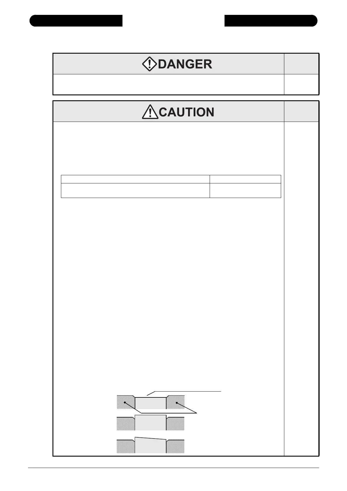
• Connect the memory cassette securely to the appropriate connector.
Unsecured connection may cause malfunctions.
Installing the cassette in a raised or tilted posture can also cause malfunctions.
Cross-sectional drawing (memory cassette installation position)
124
408
431
FX2N-10GM, FX2N-20GM, and terminal block DIN rail only
Main unit, FX
2N Series I/O extension unit/block, and FX0N/FX2N/
FX
3U Series special extension block/special adapter
DIN rail or direct mounting
Cross-section drawing (memory cassette installation condition)
Tilted cassette posture
Raised cassette
posture
Memory
cassette
Memory
cassette
Press the 4 corners in approx.
0.4mm(0.02")
Memory
cassette
PLC body
Good
Bad
Bad

 Loading...


