Home
Ricoh
Copier
A-C4
Ricoh A-C4 User Manual
4
of 1
of 1 rating
497 pages
Give review
Manual
Specs
To Next Page
To Next Page
To Previous Page
To Previous Page
Loading...
BY-PASS TRAY
20 June 2005
3-76
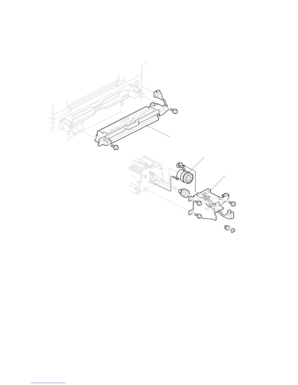
3.16.7
PAPER FEED CLUTCH REPLACEMENT
1. By-pass
tray.
2.
Paper feed unit [A] (
x2,
x2)
3.
Rear bracket [B] (
x4,
x1, bushing x1)
4.
Paper feed clutch [C] (
x1)
B195R802.WMF
B195R803.WMF
[A]
[C]
[B]
179
181
Table of Contents
Default Chapter
3
Laser Safety
3
Table of Contents
5
Installation Procedure
14
Installation Requirements
14
Environment
15
Machine Level
15
Minimum Space Requirements
16
Power Requirements
18
Installation Flow Chart
19
Main Machine Installation
20
Accessory Check
20
Installation Procedure
21
Development Unit and PCU
23
Toner Bottle
26
Paper Trays
27
Initialize TD Sensor and Developer
29
Set Paper Size for Paper Trays
30
Electrical Total Counter
31
HDD Caution Decal
31
Exposure Glass Cleaner
32
Paper Tray Unit Installation (B542)
33
Accessory Check
33
Paper Tray Unit Installation Procedure
34
1-Bin Tray Unit Installation (B544)
38
Accessory Check
38
1-Bin Tray Installation Procedure
39
Bridge Unit Installation (B538)
45
Accessory Check
45
Bridge Unit Installation Procedure
46
Two-Tray Finisher Installation (B545)
48
Accessory Check
48
Two-Tray Finisher Installation Procedure
49
Punch Unit Installation (B377)
52
Accessory Check
52
Punch Unit Installation Procedure
53
Ardf Installation (B714)
56
Accessory Check
56
Ardf Installation Procedure
57
Ardf Skew Adjustment
61
Lct Installation (B543)
62
Accessory Check
62
Lct Installation Procedure
63
Platen Cover Installation (G329)
65
Booklet Finisher Installation (B546)
66
Accessory Check
66
Booklet Finisher Installation Procedure
67
1000 Sheet Finisher (B408)
72
Accessory Check
72
1000 Sheet Finisher Installation Procedure
73
Key Counter Installation
76
Anti-Condensation Heater
79
Tray Heater
81
Tray Heater (Optional Paper Tray Unit)
81
Tray Heater (Optional Paper Tray Unit)
82
Data Overwrite Security Unit (B735)
84
Seal Check and Removal
84
Installation
85
Copy Data Security Unit (B770)
87
Accessories
87
Installation
88
Accessories
89
Scanner Accessibility Option (B815)
90
Installation
90
Pre-Installation
91
On-Site Installation
97
Preventive Maintenance Schedule
101
Pm Table
101
Replacement and Adjustment
105
General Cautions
105
Laser Unit
105
Used Toner
105
Special Tools and Lubricants
106
Special Tools
106
Lubricants
106
Front Door
107
Duplex Unit
108
Right Upper Cover
109
By-Pass Tray Unit
110
Rear Covers
111
Rear Upper Cover
111
Rear Lower Cover
111
Left Cover
112
Scanner Unit
113
Ardf
113
Exposure Glass
114
Scanner Exterior Panels, Operation Panel
115
Lens Block, Sbu Assembly
116
Original Size Sensors
117
Exposure Lamp
118
Scanner Hp Sensor/Platen Cover Sensor
119
Scanner Motor
120
Lamp Stabilizer and Scanner Motor Drive Board
121
Scanner Wire
122
Laser Unit
126
Caution Decal Locations
126
Laser Unit
127
Polygon Mirror Motor
129
Laser Synchronization Detector
130
Ld Unit
131
Laser Beam Pitch Adjustment
132
Photoconductor Unit (Pcu)
134
Pcu
134
Drum
135
Pick-Off Pawls
137
Pick-Off Pawl Position Adjustment
137
Charge Roller and Cleaning Roller
138
Drum Cleaning Blade 2
139
Drum Cleaning Blade 1
140
ID Sensor
141
Development
142
Development Unit
142
Development Filter
143
Development Roller
144
Developer
145
Td Sensor
147
Transfer Unit
148
Transfer Belt Unit
148
Transfer Belt
149
Transfer Belt Cleaning Blade and Toner Overflow Sensor
150
Paper Feed
151
Pick-Up, Separation, and Feed Rollers
151
Lower Right Cover
152
Relay/Upper Paper Feed and Lower Paper Feed Clutches
153
Upper Paper Feed Unit for Tray 1
154
Lower Paper Feed Unit for Tray 2
155
Paper End/Paper Height/Relay Sensors
156
Registration Sensor
157
Tray Lift Motor
159
Feed/Development Motor
160
Idle Roller Dust Blade
161
Registration Roller Dust Blade
162
Fusing Unit
163
Fusing Unit Removal
163
Fusing Unit Exit Guide
164
Hot Roller Strippers
165
Fusing Lamps
166
Thermistors and Thermostats
168
Hot Roller/Pressure Roller
169
Fusing Unit Side Fan
171
Fusing Unit Corner Fan
173
By-Pass Tray
174
Cover Replacement
174
By-Pass Paper Feed and Pick-Up Roller Replacement
175
By-Pass Separation Roller
176
Paper End Sensor, Pick-Up Solenoid
177
Paper Size Sensor Board Replacement
178
By-Pass Table Removal
179
Paper Feed Clutch Replacement
180
Duplex Unit
181
Duplex Cover Removal
181
Duplex Entrance Sensor Replacement
182
Duplex Exit Sensor Replacement
183
Drive Area
184
Registration Clutch, Transfer Belt Contact Clutch
184
Main Motor
185
Fusing/Exit Motor
186
Toner Supply Motor
187
Printed Circuit Boards
188
Nvram
188
High Voltage Power Supply
190
Iob
191
IOB DIP Switch Settings (SW101)
192
Bicu Board
193
Psu
194
Hdd, Controller Board
195
Copy Adjustments: Printing/Scanning
196
Printing
196
Registration - Leading Edge/Side-To-Side
196
Blank Margin
197
Main Scan Magnification
197
Parallelogram Image Adjustment
198
Scanning
199
Registration: Platen Mode
199
Magnification
199
Adf Image Adjustment
200
Registration
200
Touch Screen Calibration
201
Troubleshooting
202
Service Call Conditions
202
Summary
202
Sc Code Descriptions
203
Sc Code Descriptions
204
Recovery from Sc 925
228
Electrical Component Defects
231
Sensors
231
Switches
233
Blown Fuse Conditions
233
Leds
234
Test Points
234
Service Tables
235
Service Program Mode Operation
235
Service Mode Lock/Unlock
235
Service Program Mode Tables
236
Service Table Key
236
Service Mode Lock/Unlock
236
Service Tables
237
SP1-XXX: Feed
237
SP2-XXX: Drum
241
SP3-XXX: Process
251
SP4-XXX: Scanner
253
SP5-XXX: Mode
269
SP6-XXX: Peripherals
308
SP7-XXX: Data Log
310
SP8-XXX: Data Log2
316
Test Pattern Printing: Sp2-902
351
Test Pattern Table (SP2-902-2: IPU Test Print)
351
Test Pattern Table: SP2-902-3 Printing Test Patterns
352
Input Check
353
Main Machine Input Check: SP5-803
353
ARDF Input Check: SP6-007
357
Output Check
358
Main Machine Output Check: SP5-804
358
ARDF Output Check: SP6-008)
360
Smc Print out Lists: Sp5-990
360
Nip Band Width Adjustment: Sp1-109
361
Memory Clear: Sp5-801
362
Software Reset
364
System Settings and Copy Setting Reset
364
System Setting Reset
364
Copier Setting Reset
365
Updating the Firmware
366
Uploading/Downloading Nvram Data
367
Uploading Nvram Data (Sp5-824)
367
Downloading Nvram Data (Sp5-825)
368
Self-Diagnostic Mode
369
Self-Diagnostic Mode at Power on
369
Detailed Self-Diagnostic Mode
370
Executing Detailed Self-Diagnosis
370
User Program Mode
372
How to Use up Mode
372
UP Mode Initial Screen: User Tools/Counter Display
372
System Settings
372
Copier/Document Server Features
373
Printer, Facsimile, Scanner Settings
373
Counter
374
Dip Switches
375
Using the Debug Log
376
Switching on and Setting up Save Debug Log
376
Retrieving the Debug Log from the Hdd
380
Recording Errors Manually
380
New Debug Log Codes
381
SP5857-015 Copy SD Card-To-SD Card: any Desired Key
381
SP5857-016 Create a File on HDD to Store a Log
381
SP5857-017 Create a File on SD Card to Store a Log
381
Detailed Section Descriptions
382
Overview
382
Component Layout
382
Paper Path
384
Drive Layout
385
Board Structure
386
Block Diagram
386
Controller
388
Copy Process Overview
392
Exposure
392
Drum Charge
392
Laser Exposure
392
Development
392
Image Transfer
393
Separation
393
ID Sensor
393
Cleaning
393
Quenching
393
Scanning
394
Overview
394
Scanner Drive
395
Book Mode
395
ADF Mode
395
Original Size Detection in Platen Mode
396
Image Processing
398
Overview
398
Sbu (Sensor Board Unit)
399
Auto Image Density (Ads)
400
Ipu (Image Processing Unit)
401
Overview
401
Image Processing Modes
402
Summary of Image Processing Functions
404
Image Processing Steps and Related Sp Modes
405
Text Mode
405
Text/Photo Mode
406
Photo Mode
407
Pale (Low-Density Mode)
408
Generation Copy Mode
409
Pre-Filtering
410
Background Erase
411
Independent Dot Erase
412
Line Width Correction
413
Filtering
414
Interactive SP Codes
414
Text Mode MTF Filter
419
Text/Photo, Photo Mode Filter
420
Pale, Generation Mode Filter
421
Photo Mode Smoothing for Dithering
422
Photo Mode Grayscale
422
Photo Mode Image Quality
423
Others
424
Vertical Black Line Correction
424
Density Settings
424
ADS Level
425
Practical Application of Sp Modes
426
Solving Problems
426
Recommended Settings for MTF Filters
427
Laser Exposure
429
Overview
429
Auto Power Control (Apc)
430
Dual Beam Writing
431
Laser Beam Pitch Change Mechanism
432
Ld Safety Switches
433
Photoconductor Unit (Pcu)
434
Overview
434
Drum Cleaning
435
Drive Mechanism
436
Drum Pawls
436
Drum Toner Seals
436
Drum Charge
437
Overview
437
Charge Roller Voltage Correction
438
Correction for Environmental Conditions
438
Correction for Paper Width and Thickness
439
ID Sensor Pattern Production Timing
440
Drum Charge Roller Cleaning
440
Development
441
Overview
441
Drive Mechanism
442
Developer Mixing
442
Development Bias
443
Mechanism
443
Correction for Paper Width and Thickness (By-Pass Tray Only)
443
Toner Supply
444
Toner Bottle Replenishment Mechanism
444
Toner Supply Mechanism
445
Toner Scatter Prevention
446
Sensor Control Mode
447
Image Pixel Count Mode
448
Toner Near End/End Detection
448
Toner Near End
448
Toner End
448
Toner End Recovery
449
Toner Supply with Abnormal Sensors
449
Drum Cleaning and Toner Recycling
450
Drum Cleaning
450
Toner Recycling
450
Paper Feed
451
Overview
451
Paper Feed Drive
452
Pick-Up and Separation Roller Release Mechanism
452
Paper Lift
453
Paper End Detection
454
Paper Registration
455
Paper Size Detection
456
By-Pass Tray
457
Overview
457
By-Pass Tray Operation
458
By-Pass Paper Size Detection
459
Duplex Unit
460
Overview
460
Duplex Drive Layout
461
Duplex Basic Operation
462
Longer than A4 Lengthwise/Lt Lengthwise
462
Up to A4 Lengthwise/Lt Lengthwise
462
Duplex Unit Feed in and Exit Mechanism
463
Feed-In
463
Inversion and Exit
463
Image Transfer and Paper Separation
464
Overview
464
Belt Drive Mechanism
465
Transfer Belt Unit Contact Mechanism
465
Image Transfer and Paper Separation Mechanism
466
Transfer Belt Charge
467
Mechanism
467
Correction for Paper Width and Thickness
468
Currents Applied to Leading Edge, Image Areas - By-Pass Feed
469
Transfer Belt Cleaning Mechanism
470
Image Fusing and Paper Exit
471
Overview
471
Fusing Drive
472
Fusing Drive Release Mechanism
472
Fusing Entrance Guide Shift Mechanism
473
Exit Guide Plate and De-Curler Rollers
473
Pressure Roller
474
Cleaning Mechanism
475
Hot Roller Stripper Cleaning
476
Small Jobs
476
Medium Jobs
477
Large Jobs
477
SP Settings for Post-Job Cleaning
478
Fusing Temperature Control
479
Temperature Control
480
Fusing Idling Temperature
481
Cpm down for Thick Paper
482
Cooling and Overheat Protection
483
Overheat Protection
484
Energy Saver Modes
485
Overview
485
Energy Saver Mode
486
Entering the Energy Saver Mode
486
What Happens in Energy Saver Mode
486
Return to Stand-By Mode
486
Auto off Mode
487
Entering off Stand-By and off Modes
487
Off Stand-By Mode
487
Off Mode
488
Returning to Stand-By Mode
488
Specifications
489
General Specifications
489
Power Consumption
490
Noise Emission
490
Machine Configuration
491
Optional Equipment
493
4
Based on 1 rating
Ask a question
Give review
Questions and Answers:
Need help?
Do you have a question about the Ricoh A-C4 and is the answer not in the manual?
Ask a question
Ricoh A-C4 Specifications
General
Brand
Ricoh
Model
A-C4
Category
Copier
Language
English
Related product manuals
Ricoh A250
33 pages
Ricoh aficio 1013
384 pages
Ricoh Aficio 2020
72 pages
Ricoh Aficio 2016
72 pages
Ricoh Aficio 2035
132 pages
Ricoh Aficio C3002
244 pages
Ricoh Aficio MP171
260 pages
Ricoh Aficio MP C3000
166 pages
Ricoh Aficio 2051/2060/2075
176 pages
Ricoh MD-P2
356 pages
Ricoh MP C4504
24 pages
Ricoh MP C2004 series
36 pages