Garmin G300 Pilot’s Guide
190-00921-00 Rev. D 57
Flight Instruments
System
Overview
Flight
Instruments EIS
COM
Interface
GPS
Navigation
Flight
Planning
Hazard
Avoidance
Additional
Features
Integrated
Autopilot Annun/Alerts Appendix Index
mA n u A l cDi Sc A l e Se l e c t i o n
The Automatic CDI Scale Selection will resume once the default determining
factor for the current phase of flight matches the user-selected CDI scale.
Adjusting the CDI scale:
From the PFD (dual display) or PFD Page (single display), press the RNG Key
down arrow to zoom in (decrease CDI scale), or the up arrow to zoom out
(increase CDI scale).
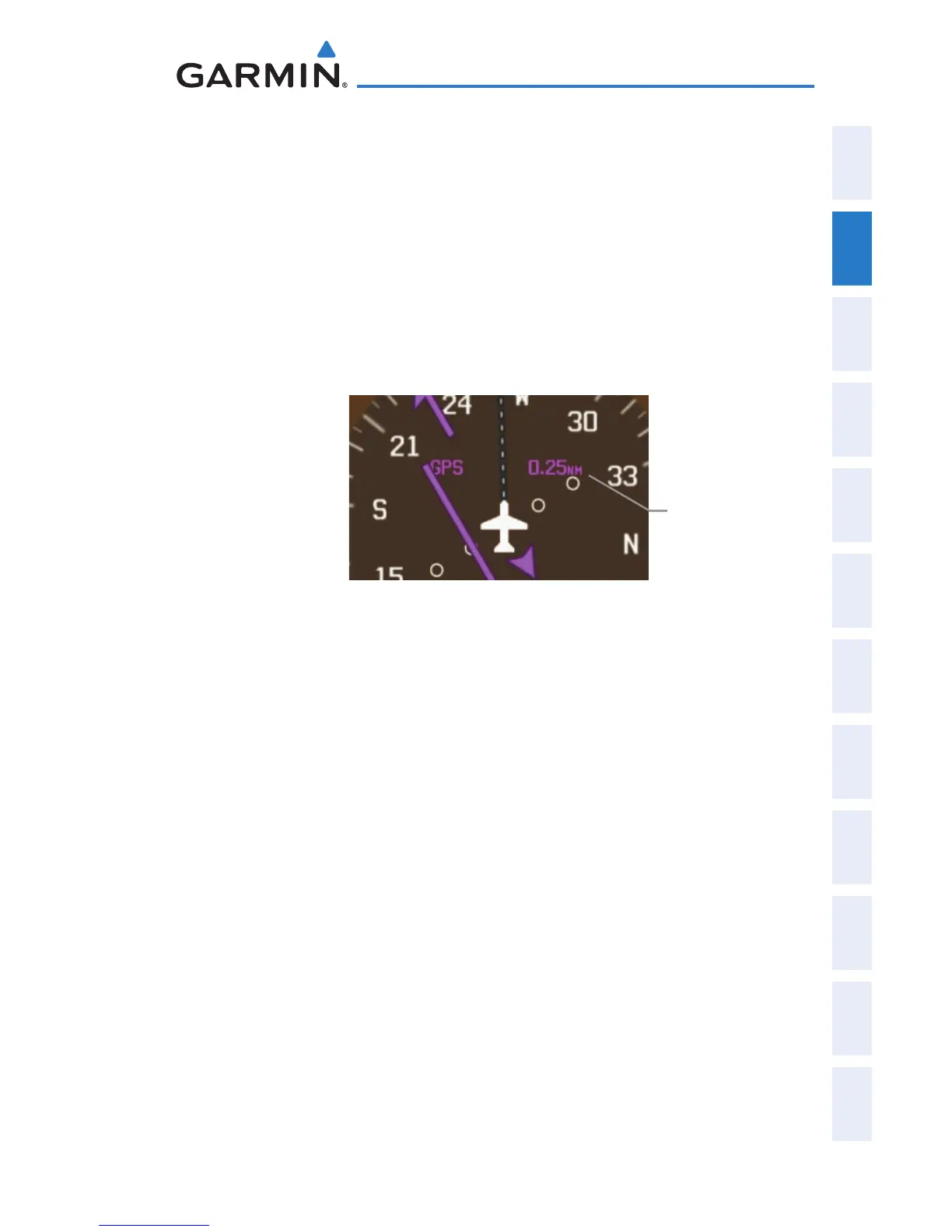
The current CDI scale appears in the upper right corner of the HSI.
Horizontal Situation Indicator (HSI)
Current
CDI Scale
BEARING POINTERS AND INFORMATION WINDOWS
Two bearing pointers and associated information can be displayed on the HSI
for GPS sources. The bearing pointers are light blue and are single-line (Bearing
Pointer 1) or double-line (Bearing Pointer 2). A pointer symbol is shown in the
information windows to indicate the navigation source. The bearing pointers
never override the CDI and are visually separated from the CDI by a white ring
(shown when the bearing pointers are selected but not necessarily visible due to
data unavailability).
When a bearing pointer is displayed, its associated information window is also
displayed. The Bearing Information Windows are displayed at the lower sides of
the HSI. The following information may be displayed in the Bearing Information
Windows:
•Bearingsource(GPS)
• Pointericon
•Station/waypointidentier(GPS)
•GPS-derived great circle distance
to bearing source
 Loading...