ENGINE
L3540-II, L4240-II, L5040-II, L5240-II, L5740-II , WSM
1-S17
[4] FUEL SYSTEM
Injection Timing
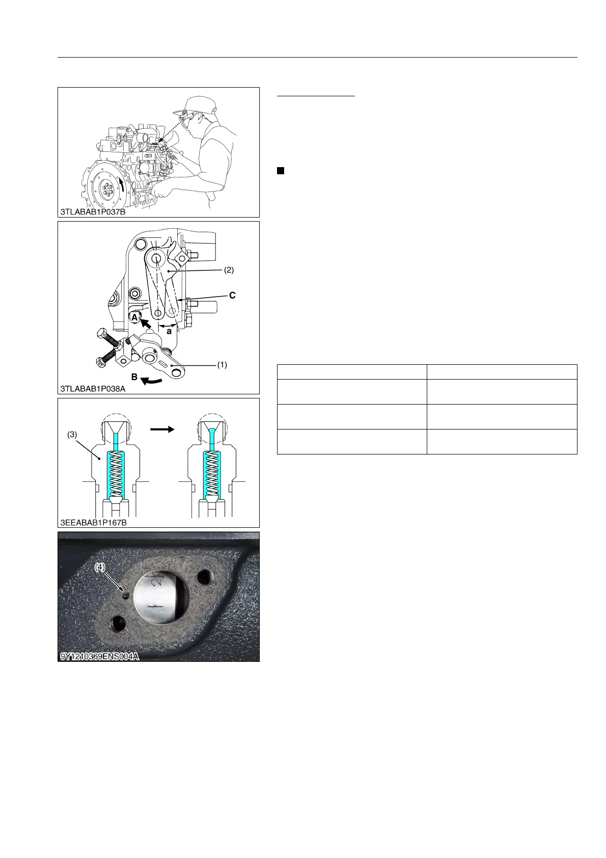
1. Remove the stop solenoid.
2. Remove the injection pipes and nozzle.
3. Set the speed control lever to maximum fuel discharge position.
(Reference)
• Turn the flywheel with screwdriver.
• For V2003-M, V2203-M and V2403-M, the pumps have a
displacement angle. In adjusting the injection timing, pull
the stop lever (2) from its free position by 0.267 ± 0.035 rad
(15.3 ± 2 °) toward the stop position.
4. Turn the flywheel counterclockwise (facing the flywheel) until
the fuel fills up to the hole of the delivery valve holder for 1st
cylinder.
5. Turn the flywheel further and stop turning when the fuel begins
to flow over, to get the present injection timing.
6. (The flywheel has mark 1TC and four lines indicating every
0.087 rad (5 °) of crank angle from 0.175 rad (10 °) to 0.436 rad
(25 °) before mark 1TC) Calculate the angle which the center of
the window points out. If the calculation differs from specified
injection timing, add or remove the shim to adjust.
(Injection Timing)
(To be continued)
Model Injection timing
L3540-II
L4240-II
0.30 to 0.33 rad (17 to 19 °)
before T.D.C.
L5040-II
0.13 to 0.15 rad (7.5 to 9.0 °)
before T.D.C.
L5240-II
L5740-II
0.15 to 0.17 rad (8.5 to 10. °)
before T.D.C.
(1) Speed Control Lever
(2) Stop Lever
(3) Delivery Valve Holder
(4) Timing Mark
A: To STOP Position
B: To Max. Speed Position
C: Stop Lever in Free Position
a: 0.267 ± 0.035 rad (15.3 ± 2 °)
 Loading...


