TRANSMISSION
L3540-II, L4240-II, L5040-II, L5240-II, L5740-II , WSM
3-S32
[3] HYDROSTATIC TRANSMISSION (HST) MODEL
(1) Electrical Adjusting [Adjustment with Electronic Instrument Panel
(Intellipanel)]
• Before executing the following fine-adjustment, refer to "Testing, Setting and Adjusting by Electronic
Instrument Panel" of an Electrical System section.
9Y1211167TRS0025US0
Adjustment of Transmission Model Input Mode
• When the electronic instrument panel or range gear shift
sensor was replaced, this adjustment is required.
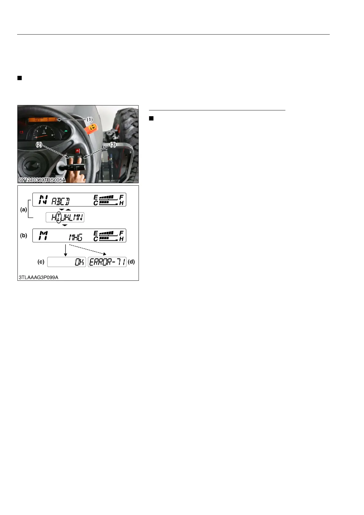
1. Set the range gear shift lever to the M position.
2. Push down both the display mode switch (2) and the travel
speed switch (3) at once, continue holding switches, and then
turn the main switch to "ON" position.
3. The "Mode Selection Display" (a) is indicated on the LCD (1).
And release the switches.
4. Press the display mode switch (2) to move the flashing part, and
flash the "I".
5. Hold down the display mode switch (2) for more than 2 seconds
at this condition, and the buzzer rings and Mode I is selected.
6. "MHG" is displayed (b), and the existing symbol setting is
flashing.
7. Press the display mode switch (2) to move the flashing part, and
flash the "H" of the HST model.
8. Hold down the display mode switch (2) for more than 2 seconds
at this condition, and the buzzer rings.
9. "OK" is displayed (c): Lever sensor voltage is as specified.
10. "ERROR 71" is displayed (d): Lever sensor voltage is not
specified.
In this case;
• Check to see that the range gear shift lever is at M position.
• Check the lever sensor voltage in the Test Mode (Mode
"A") (Refer to "9. TESTING, SETTING AND ADJUSTING
BY INSTRUMENT PANEL" at "ELECTRICAL SYSTEM"
section). If out of specification, replace the sensor.
9Y1211167TRS0026US0
(1) Liquid Crystal Display (LCD)
(2) Display Mode Switch
(3) Travel Speed Switch
(a) Mode Selection Display
(b) Information Display
(c) Correct Preserving Display
(d) Error Display
 Loading...


