ELECTRICAL SYSTEM
L3540-II, L4240-II, L5040-II, L5240-II, L5740-II , WSM
9-S71
5. DISASSEMBLING AND ASSEMBLING
[1] STARTER
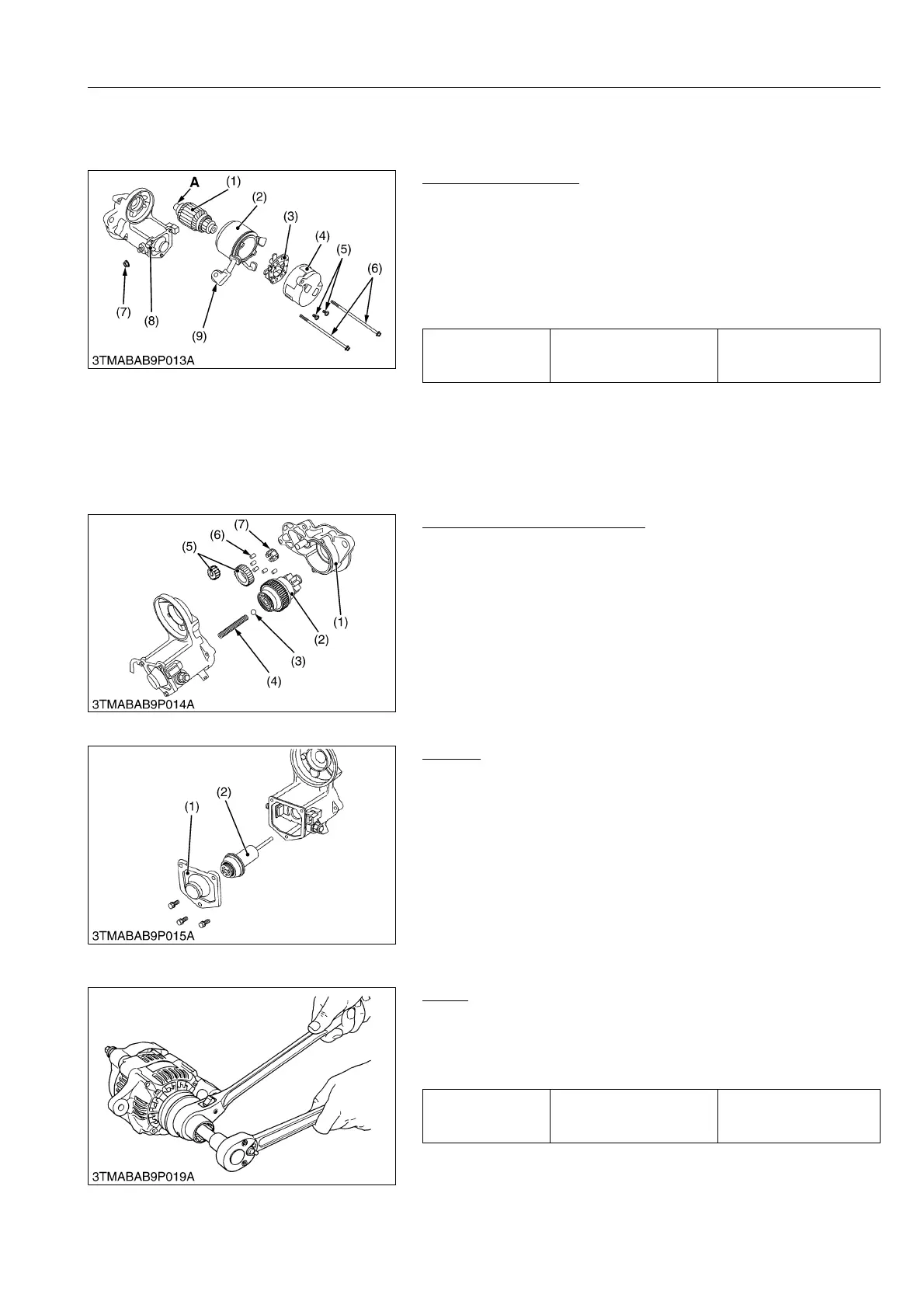
Disassembling Motor
1. Disconnect the connecting lead (9) from the magnet switch (8).
2. Remove the screws (6), and then separate the end frame (4),
yoke (2) and armature (1).
3. Remove the two screws (5), and then remove the brush holder
(3) from the end frame (4).
(When reassembling)
• Apply grease to the spline teeth "A" of the armature (1).
9Y1211167ELS0095US0
Disassembling Magnet Switch
1. Remove the drive end frame (1) mounting screws.
2. Remove the overrunning clutch (2), ball (3), spring (4), gears
(5), rollers (6) and retainer (7).
(When reassembling)
• Apply grease to the gear teeth of the gears (5) and overrunning
clutch (2), and ball (3).
WSM000001ELS0021US0
Plunger
1. Remove the end cover (1).
2. Remove the plunger (2).
WSM000001ELS0022US0
[2] ALTERNATOR
Pulley
1. Secure the hexagonal end of the pulley shaft with a
double-ended ratchet wrench as shown in the figure.
2. Loosen the pulley nut with a socket wrench and remove it.
(When reassembling)
WSM000001ELS0023US0
Tightening torque Nut (7)
5.9 to 11 N·m
0.60 to 1.2 kgf·m
4.4 to 8.6 lbf·ft
(1) Armature
(2) Yoke
(3) Brush Holder
(4) End Frame
(5) Screw
(6) Screw
(7) Nut
(8) Magnet Switch
(9) Connecting Lead
A: Spline Teeth
(1) Drive End Frame
(2) Overrunning Clutch
(3) Ball
(4) Spring
(5) Gear
(6) Roller
(7) Retainer
(1) End Cover (2) Plunger
Tightening torque Pulley nut
58.4 to 78.9 N·m
5.95 to 8.05 kgf·m
43.1 to 58.2 lbf·ft
 Loading...


