ELECTRICAL SYSTEM
L3540-II, L4240-II, L5040-II, L5240-II, L5740-II , WSM
9-S47
Proportional Reducing Valve Resistance
1. Measure the resistance between the valve terminals.
2. It is OK if the resistance comes to have shown in the table
below.
• When replacing the proportional reducing valve be sure to
adjust the mode "F".
9Y1211167ELS0049US0
Shift Solenoid Resistance
1. Measure the resistance between each connector terminal and
each valve body.
2. It is OK if the resistance comes to have shown in the table
below.
• It is not necessary to adjust any kind of mode.
9Y1211167ELS0050US0
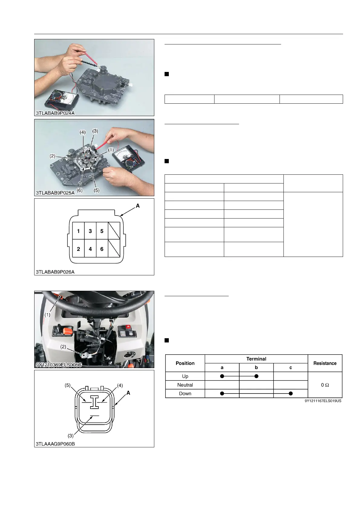
(4) Checking Sensor and Switch for HST Model
H-DS Lever Continuity
1. Remove the steering post cover 1.
2. Disconnect the connector (2).
3. Measure the resistance between connector terminals, referring
to the table below.
4. If the measurement does not between as table, switch is faulty.
• It is not necessary to adjust any kind of mode.
9Y1211167ELS0051US0
Resistance Reference value 8 to 9 Ω
Measuring point
Resistance
Solenoid Connector terminal
(1) Solenoid 1 1
11 to 15 Ω
(2) Solenoid 2 2
(3) Solenoid 3 3
(4) Solenoid 4 4
(5) Solenoid 5
(Sub- range)
5
(6) Solenoid 6
(Main range)
6
A: Connector of Solenoid Side
(1) H-DS Lever
(2) H-DS Connector
(3) Terminal a
(4) Terminal b
(5) Terminal c
A: Connector of H-DS Lever Side
 Loading...


