HYDRAULIC SYSTEM
L3540-II, L4240-II, L5040-II, L5240-II, L5740-II , WSM
8-M21
6. AUXILIARY CONTROL VALVE (IF EQUIPPED)
[1] DOUBLE ACTING TYPE
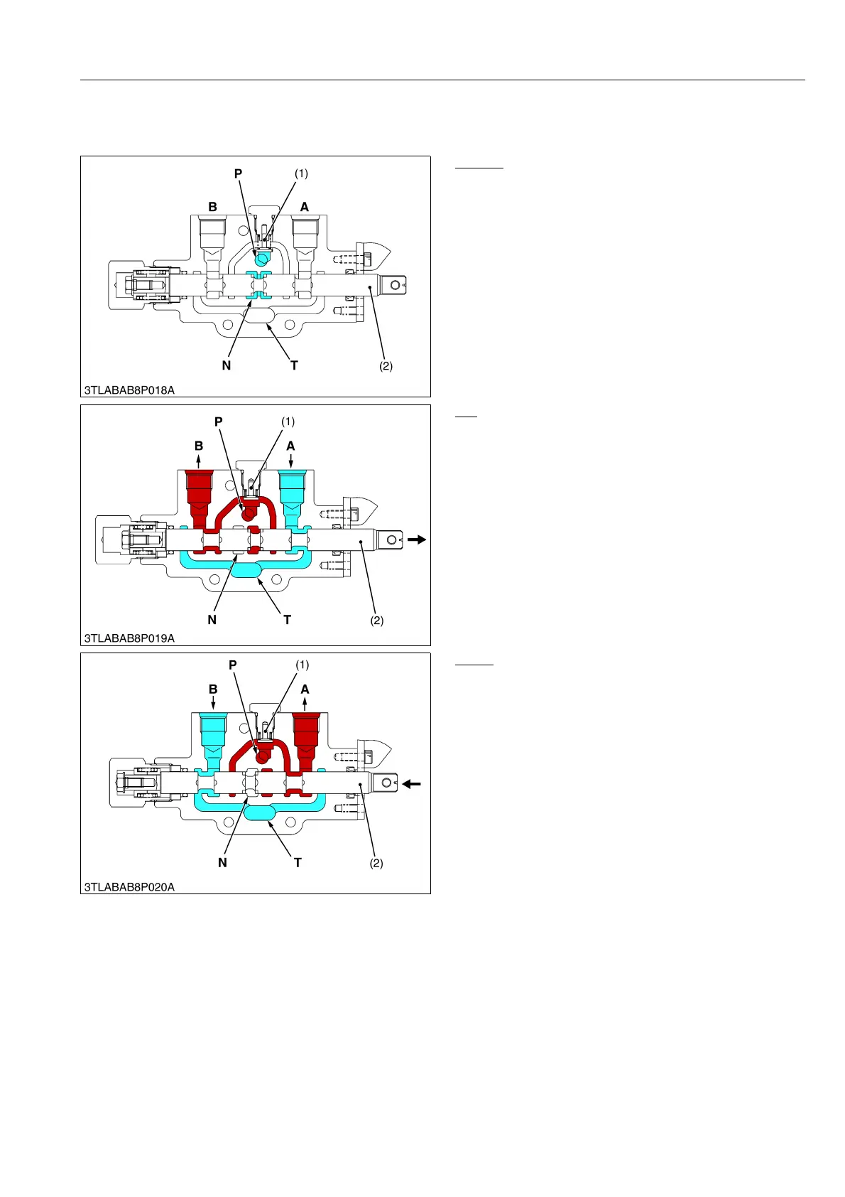
Neutral
Pressure-fed oil from the hydraulic pump is delivered
into the P port, and flows to the position control valve via
N port.
9Y1211167HYM0025US0
Lift
When the spool (2) is moved in the direction of the
arrow, the pressure-fed oil in the P port opens the check
valve (1) and flows to the implement cylinder via B port.
Return oil from the implement cylinder flows from the
A port to the transmission case through T port.
9Y1211167HYM0026US0
Down
When the spool (2) is moved in the direction of the
arrow, the pressure-fed oil in the P port opens the check
valve (1) and flows to the implement cylinder via A port.
Return oil from the implement cylinder flows from the
B port to the transmission case through T port.
9Y1211167HYM0027US0
(1) Check Valve
(2) Spool
A: A Port
(Implement Cylinder)
B: B Port
(Implement Cylinder)
P: Pump Port
N: Neutral Port
T: Tank Port
(1) Check Valve
(2) Spool
A: A Port
(Implement Cylinder)
B: B Port
(Implement Cylinder)
P: Pump Port
N: Neutral Port
T: Tank Port
(1) Check Valve
(2) Spool
A: A Port
(Implement Cylinder)
B: B Port
(Implement Cylinder)
P: Pump Port
N: Neutral Port
T: Tank Port
 Loading...


