ELECTRICAL SYSTEM
L3540-II, L4240-II, L5040-II, L5240-II, L5740-II , WSM
9-S40
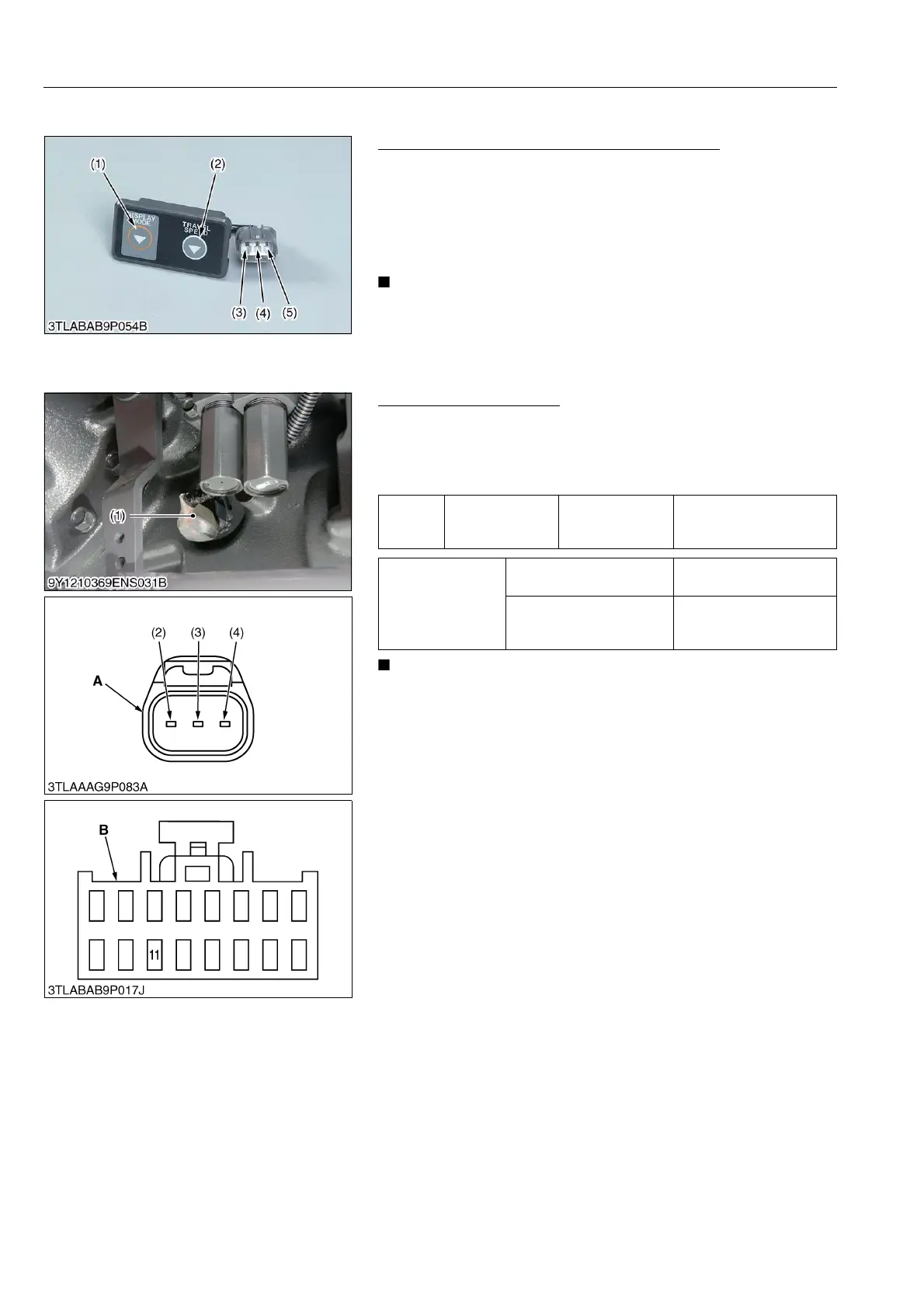
(3) Checking Sensor and Switch
Display Mode Switch and Travel Speed Switch
1. Check the resistance between terminal a (3) and c (5) while
pushing the display made switch (1).
2. It is OK if 0 ohm is indicated.
3. Check the resistance between terminal b (4) and c (5) while
pushing the travel speed switch (2).
4. It is OK if 0 ohm is indicated.
• It is not necessary to adjust any kind of mode.
9Y1211167ELS0038US0
Travelling Speed Sensor
1. Check the voltage of the sensor in mode "A".
2. Measure the voltage and resistance of the wire harness
connector.
3. If measured values are normal, the switch is damaged.
• It is not necessary to adjust any kind of mode.
9Y1211167ELS0039US0
(1) Display Mode Switch
(2) Travel Speed Switch
(3) Terminal a
(4) Terminal b
(5) Terminal c
Voltage
Main switch at
"ON" position
Terminal 1 of the
sensor connector
– chassis
Approx. battery voltage
Resistance
Terminal 3 of the sensor
connector – chassis
0 Ω
Terminal 2 of the sensor
connector – Terminal 11 of
the panel connector
0 Ω
(1) Traveling Speed Sensor
(2) Terminal 1
(3) Terminal 2
(4) Terminal 3
A: Connector of Wire Harness Side
B: Panel Connector B of Wire
Harness
C: ECU Connector of Wire Harness
Side
 Loading...


