STEERING
L3540-II, L4240-II, L5040-II, L5240-II, L5740-II , WSM
7-M2
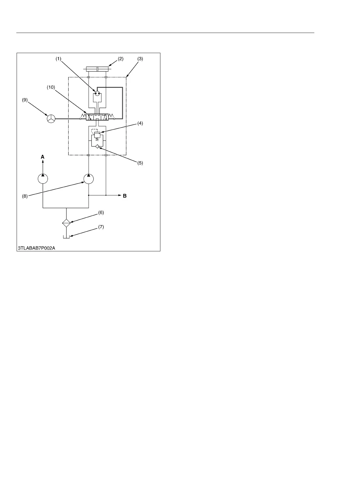
2. HYDRAULIC CIRCUIT
When the engine starts, the hydraulic pump (8)
pressure-feeds the oil, drawn from the transmission case
(7) through the oil filter (6), to the steering controller (3).
The oil which has entered steering controller (3) is
directed to control valve (10).
As the steering wheel is turned, control valve (10)
operates and the oil passes through gerotor (1) and into
steering cylinder (2). The cylinder rod then moves to
control the directional movement of the front wheels.
Return oil from steering cylinder (2) passes through
control valve (10) is sent to the PTO clutch valve, HST,
GST valve, etc..
When the engine is not operating, and the steering
wheel is turned, gerotor (1) rotates to supply oil to
steering cylinder (2). Thus the machine can be steered
manually.
9Y1211167STM0002US0
(1) Gerotor
(2) Steering Cylinder
(3) Steering Controller
(4) Relief Valve
(5) Check Valve
(6) Oil Filter
(7) Transmission Case
(8) Hydraulic Pump
(9) Steering Wheel
(10) Control Valve
A: To Three Point Hydraulic
System and Others
B: To PTO Clutch Valve, HST,
GST Valve, etc.
 Loading...


