ELECTRICAL SYSTEM
L3540-II, L4240-II, L5040-II, L5240-II, L5740-II , WSM
9-S54
(2) Safety Switch
PTO Switch
1) Connector Voltage
1. Remove the PTO switch connector.
2. Turn the main switch "ON" position.
3. Measure the voltage across terminal 2 (Harness) and chassis.
4. If the voltage differs from battery voltage, the wiring harness, or
fuse is damaged.
2) PTO Switch Continuity
1. Remove the PTO switch connector.
2. Check the continuity with an ohmmeter across the terminal 1 (a)
and terminal 2 (b), terminal 2 (b) and terminal 3 (c).
3. If connection does not change, PTO switch is faulty.
9Y1211167ELS0064US0
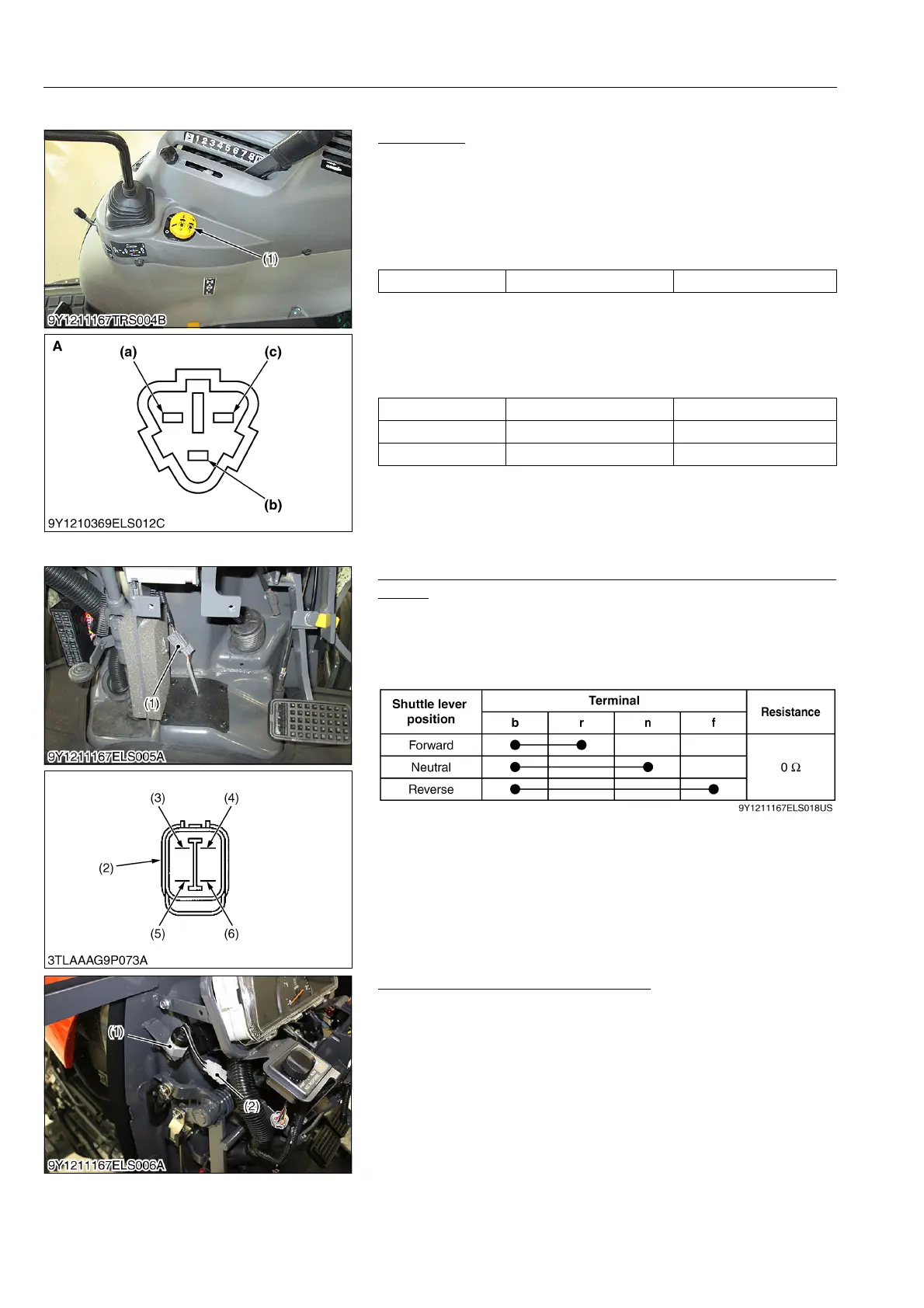
Shuttle Switch Continuity (For Manual Transmission and GST
Model)
1. Remove the steering post under cover.
2. Disconnected the shuttle switch connector (1).
3. Measure the resistance across four terminal referring to the
table below.
4. If 0 ohm is not indicated, the shuttle switch is faulty.
9Y1211167ELS0065US0
Clutch Pedal Switch (For HST Model)
1. Remove the panel cover.
2. Disconnect the clutch pedal switch connector (2).
3. Measure the resistance between connector terminals while
pushing the clutch pedal switch.
4. If 0 ohm is not indicated, switch is faulty.
9Y1211167ELS0066US0
Voltage Terminal 2 – Chassis Approx. battery voltage
Position Terminal 1 – terminal 2 Te rm in al 2 – terminal 3
OFF 0 Ω Infinity
ON Infinity 0 Ω
(1) PTO Switch (a) Terminal 1
(b) Terminal 2
(c) Terminal 3
A: Connector of the PTO switch side
(1) Shuttle Switch
(2) Connector of Switch Side
(3) Terminal b
(4) Terminal r
(5) Terminal n
(6) Terminal f
(1) Clutch Pedal Switch (2) Clutch Pedal Switch Connector
 Loading...


