HYDRAULIC SYSTEM
L3540-II, L4240-II, L5040-II, L5240-II, L5740-II , WSM
8-S17
[2] THREE POINT HITCH HYDRAULIC BLOCK ASSEMBLY
(1) Separating Hydraulic Block Assembly
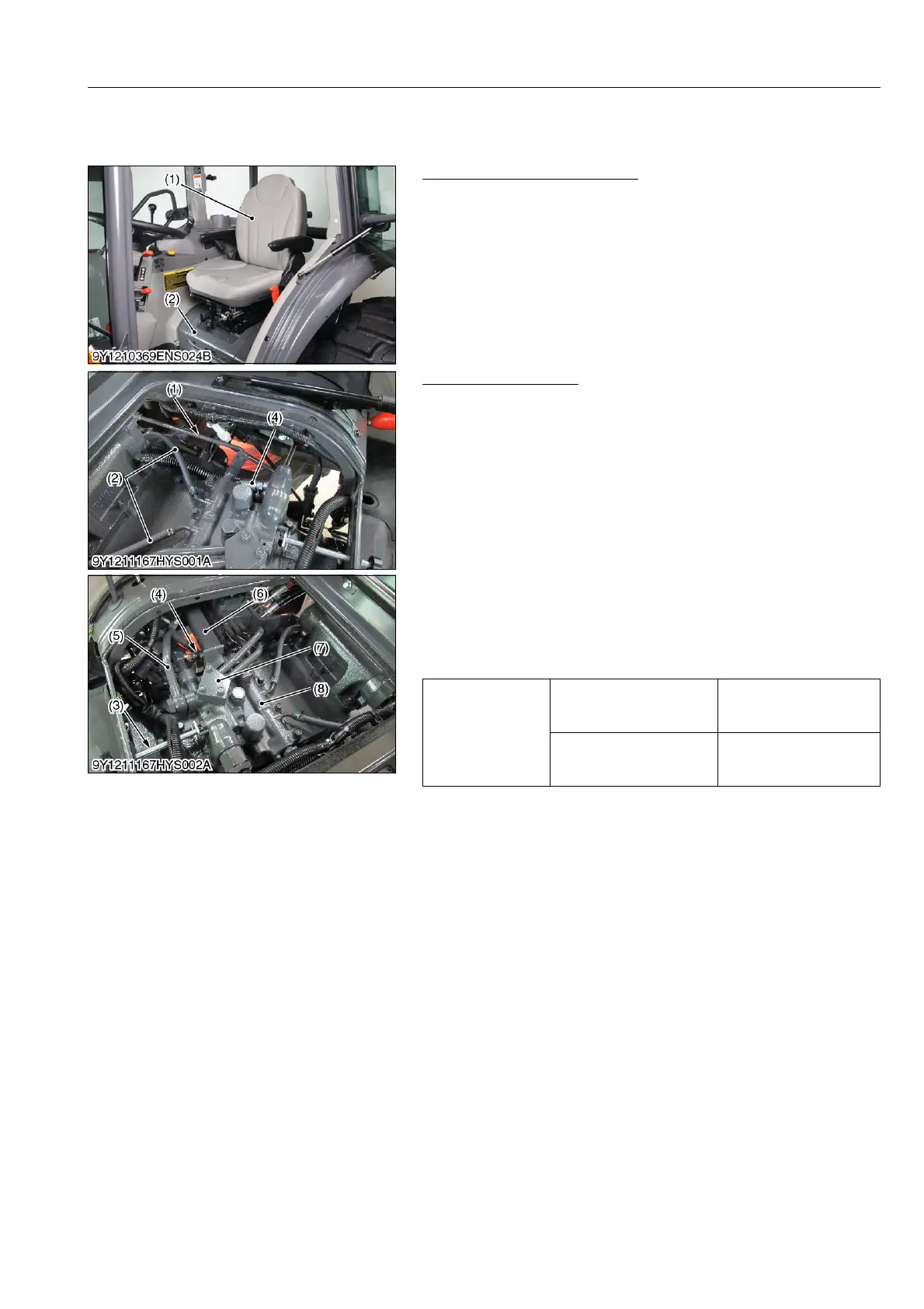
Seat, Seat Bracket and Cover
1. Remove the seat switch connector.
2. Remover the seat (1).
3. Remove the seat bracket (2).
9Y1211167HYS0018US0
Rear Hydraulic Block
1. Disconnect the position control feedback rod (1) and return
hoses (2).
2. Remove the lowering speed adjusting valve joint shaft (3).
3. Disconnect the hydraulic cylinder hoses (4) and delivery pipe
(5).
4. Remove the position control link bracket (6) and position control
rod.
5. Remove the hydraulic pipe (7).
6. Remove the rear hydraulic block (8).
(When reassembling)
• Install the copper washers firmly.
• Visually inspect the gasket, if damaged replace with new one.
• After reassembling, be sure to adjust the position control
feedback rod length. (Refer to "4. CHECKING AND
ADJUSTING" in this section.)
9Y1211167HYS0019US0
(1) Seat (2) Seat Bracket
Tightening torque
Hydraulic cylinder hose
retaining nut
35 to 48 N·m
3.5 to 4.9 kgf·m
26 to 35 lbf·ft
Delivery pipe joint bolt
49 to 68 N·m
5.0 to 7.0 kgf·m
37 to 50 lbf·ft
(1) Feedback Rod
(2) Return Hose
(3) Lowering Speed Adjusting Valve
Joint Shaft
(4) Hydraulic Cylinder Hose
(5) Delivery Pipe
(6) Position Control Link Bracket
(7) Hydraulic Pipe
(8) Rear Hydraulic Block
 Loading...


