ENGINE
L3540-II, L4240-II, L5040-II, L5240-II, L5740-II , WSM
1-S36
6. DISASSEMBLING AND ASSEMBLING
[1] OUTER PARTS
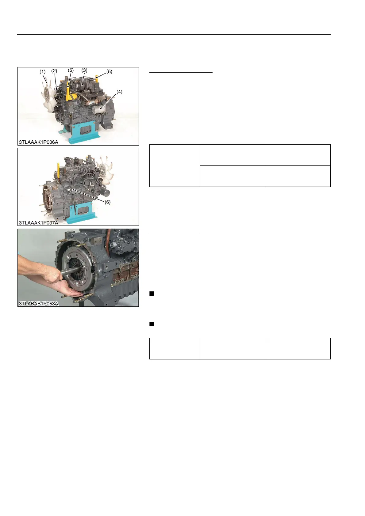
Outer Parts of Engine
1. Remove the cooling fan (1) and fan pulley (2).
2. Remove the turbo charger (3).
3. Remove the starter motor (4).
4. Remove the hydraulic pump (6) with pump holder and
regulating valve. [Manual Transmission and GST model]
Remove the hydraulic pump (6) with pump holder. [HST model]
(When reassembling)
• Be sure to adjust the fan belt tension. (Refer to "7-[4] CHECK
POINTS OF EVERY 100 HOURS" at "G. GENERAL" section.)
9Y1211167ENS0025US0
Clutch Assembly
1. Remove the clutch from the flywheel.
(When reassembling)
• Direct the shorter end of the clutch disc boss toward the
flywheel.
• Apply molybdenum disulphide (Three Bond 1901 or equivalent)
to the splines of clutch disc boss.
• Install the pressure plate, nothing the position of straight pins.
• Align the center of disc and flywheel by inserting the clutch
center tool. (Refer to "8. SPECIAL TOOLS" at "G.
GENERAL" section.)
• Do not allow grease and oil on the clutch disc facing.
9Y1211167ENS0026US0
Tightening torque
Alternator mounting screw
(M10)
40 to 44 N·m
4.0 to 4.5 kgf·m
29 to 32 lbf·ft
Tension adjusting Screw
(M8)
18 to 20 N·m
1.8 to 2.1 kgf·m
13 to 15 lbf·ft
(1) Cooling Fan
(2) Fan Pulley
(3) Turbo Charger
(4) Starter Motor
(5) Engine Hock
(6) Hydraulic Pump
Tightening torque Clutch mounting screws
24 to 27 N·m
2.4 to 2.8 kgf·m
18 to 20 lbf·ft
 Loading...


