CLUTCH
L3540-II, L4240-II, L5040-II, L5240-II, L5740-II , WSM
2-S18
6. DISASSEMBLING AND ASSEMBLING
Clutch Assembly
1. Remove the clutch from the flywheel.
(When reassembling)
• Direct the shorter end of the clutch disc boss toward the
flywheel.
• Apply molybdenum disulphide (Three Bond 1901 or equivalent)
to the splines of clutch disc boss.
• Install the pressure plate, noting the position of straight pins.
• Align the center of disc and flywheel by inserting the clutch
center tool. (Refer to "8. SPECIAL TOOLS" at "G.
GENERAL" section.)
• Do not allow grease and oil on the clutch disc facing.
9Y1211167CLS0021US0
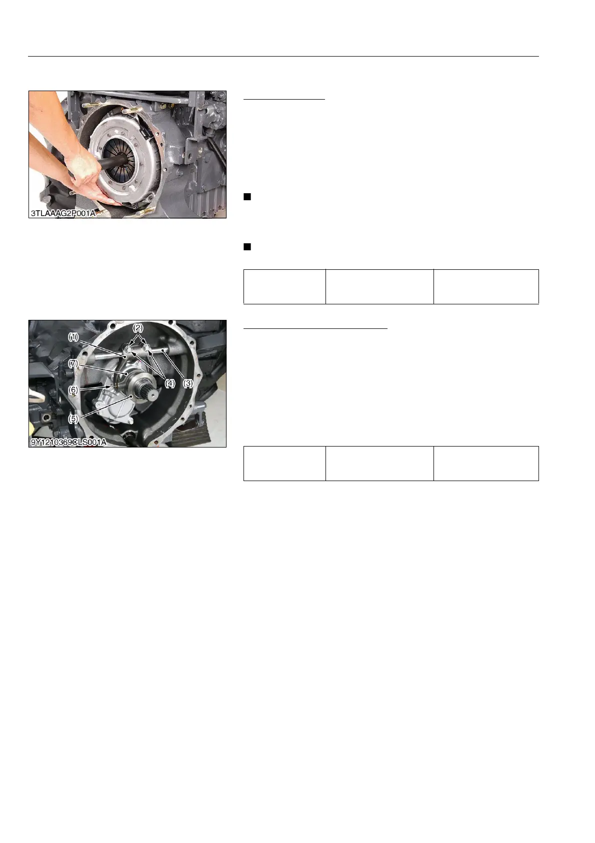
Release Hub and Clutch Lever
1. Draw out the clutch release hub (7) and the release bearing (5)
as a unit.
2. Remove the release fork setting screws (4) and fork keys (2).
3. Draw out the clutch lever (3) to remove the release fork (1).
(When reassembling)
• Make sure the direction of the release fork (1) is correct.
• Be sure to set the fork keys (2) inside the release fork (1).
• Inject grease to the release hub (7).
• Be sure to set the snap pins (6).
9Y1211167CLS0022US0
Tightening torque Clutch mounting screws
24 to 27 N·m
2.4 to 2.8 kgf·m
18 to 20 lbf·ft
Tightening torque Release fork setting screws
24 to 27 N·m
2.4 to 2.8 kgf·m
18 to 20 lbf·ft
(1) Release Fork
(2) Fork Key
(3) Clutch Lever
(4) Setting Screw
(5) Release Bearing
(6) Snap Pin
(7) Release Hub
 Loading...


