Trigger setups Set up a Logic State trigger
Set up a Logic State trigger
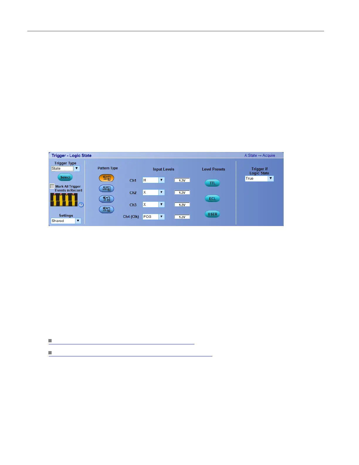
From the Trig menu, select Logic State Setup.
Overview
Use the controls in this window to set up the Logic State trigger parameters.
To use
For information on the controls, click the buttons.
Behavior
Use the Logic State trigger to trigger the instrument when all of the logic inputs to the selected logic
function cause the function to be True or False when the clock input changes state.
Channels 1, 2, and 3 represent the data inputs, and channel 4 represents the clock input. (The clock input is
channel 2 on 2-channel m odels.) You can set each data channel to be logic high, logic low, or a "don't care"
value. You can set the channel 4 input to a rising or falling clock edge (or channel 2 on 2-channel
models). Use the multipurpose knobs to change the threshold voltages for logic levels other than TTL.
The Pattern Type buttons set the Boolean logic function for the trigger.
What do you want to do next?
Learn more about other trigger types. (see page 386)
Return to the Trigger Setup control window. (see page 385)
Set up a Timeout trigger
From the Trig menu, select Timeout Setup.
436 DSA/DPO70000D, MSO/DPO/DSA70000C, DPO7000C, and MSO/DPO5000 Series
 Loading...


