Oscilloscope Reference State trigger
State trigger
A state trigger occurs when the inputs to the logic function cause the function to become True or False at
the time the clock input changes state. When you use a state trigger, you define:
The precondition for logic input channels 1 through 3
The direction of the state change for the clock input, channel 4
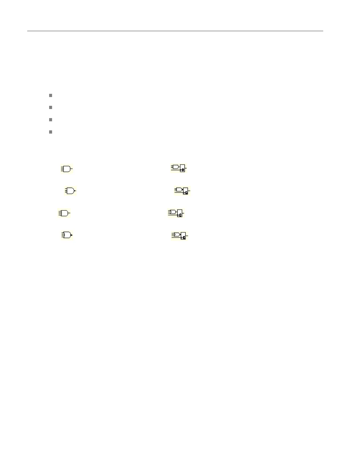
The Boolean logic function: AND, NAND, OR, or NOR
The condition for triggering: the Boolean function becomes True (logic high) or False (logic low)
State trig
ger logic conditions are summarized in the following table.
Pattern State Definitio
n
1
,
2
AND
Clocked AND
If all the
preconditions selected for
the logic inputs
3
are TRUE, then the
instrument triggers.
NAND
Clocked NAND
If not all of the preconditions s elected
for the
logic inputs
3
are TRUE, then
the instrument triggers.
OR
Clocke
dOR
If any of the preconditions selected for
the logic inputs
3
are TRUE, then the
instr
ument triggers.
NOR
Clocked NOR
If non
e of the preconditions selected
for the logic inputs
3
are TRUE, then
the instrument triggers.
xxx
1
For state triggers, the definition must be met at the time the clock input changes state.
2
The definitions given here are correct for the Goes TRUE setting in the Trigger When menu. If that menu is set to Goes False, swap the definitio n for
AND with that for NAND and for OR with NOR for both pattern and state types.
3
The logic inputs are channels 1, 2, 3, and 4 when using Pattern triggers. For State triggers, channel 4 becomes the clock input, leaving
the r
emaining channels as logic inputs.
708 DSA/DPO70000D, MSO/DPO/DSA70000C, DPO7000C, and MSO/DPO5000 Series
 Loading...


