Vertical Setups Coupling C ontrols
Coupling Controls
From the Vertical menu, select Coupling.
Overview
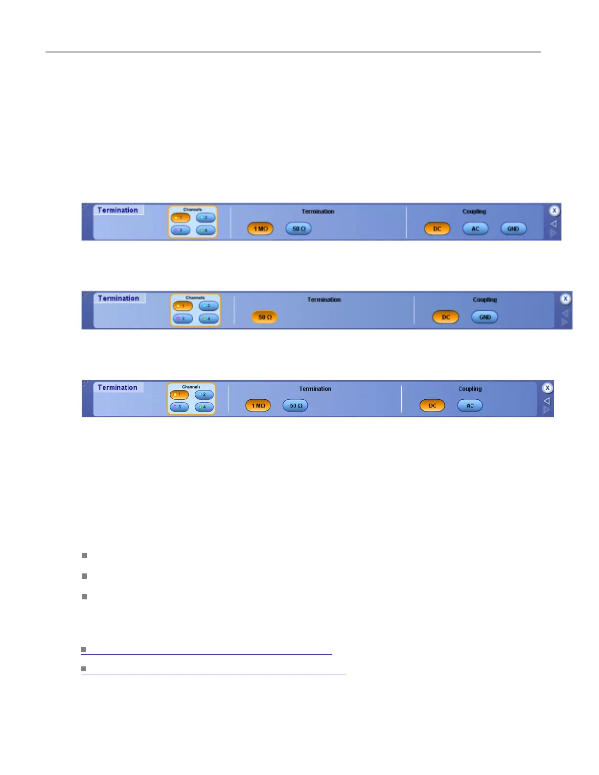
Use the Termination control window to select the input coupling.
For ≥4 GHz model oscilloscopes, DC coupling is the only selection.
The following screen appears on MSO/DPO5000 Series instruments:
To use
1. Click a Channels button to select the vertical input channel.
2. Click one of the Coupling buttons to couple the signal from the probe to the instrument.
Behavior
Select DC coupling to display a waveform with AC and D C components.
Select AC coupling to display a waveform with its DC component removed.
Select GND to display a zero-volt waveform. Use this selection to establish the ground reference
point on the display.
What do you want to do next?
Learn m ore about the Vertical controls. (see page 891)
Learn more about the Bandwidth controls. (see page 494)
492 DSA/DPO70000D, MSO/DPO/DSA70000C, DPO7000C, and MSO/DPO5000 Series
 Loading...


