Oscilloscope R eference Signal connection
Signal connection
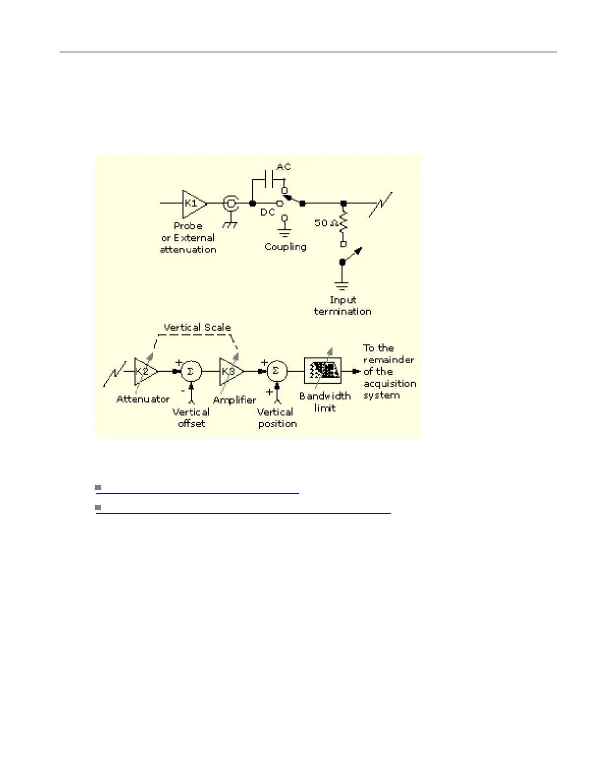
This diagram displays the signa l connection model for each input channel.
What do you want to do next?
Learn more about coupling. (see page 680)
Learn more about the vertical acquisition s ystem. (see page 681)
Probes and signal connection
Select the probe or cable that brings the signal into the instrument. Choose the probe or cable that best fits
your acquisition task, whether it is connecting an active probe to test a digital circuit, or connecting to a
test fixture through BNC cables to characterize a device. The connection to the instrument depends on
your application.
Up to four acquisition channels are available. You can display each channel as a waveform or use the
channel data to create other waveforms, such as math and reference waveforms.
DSA/DPO70000D, MSO/DPO/DSA70000C, DPO7000C, and MSO/DPO5000 Series 677
 Loading...


