FEATURES
1-8
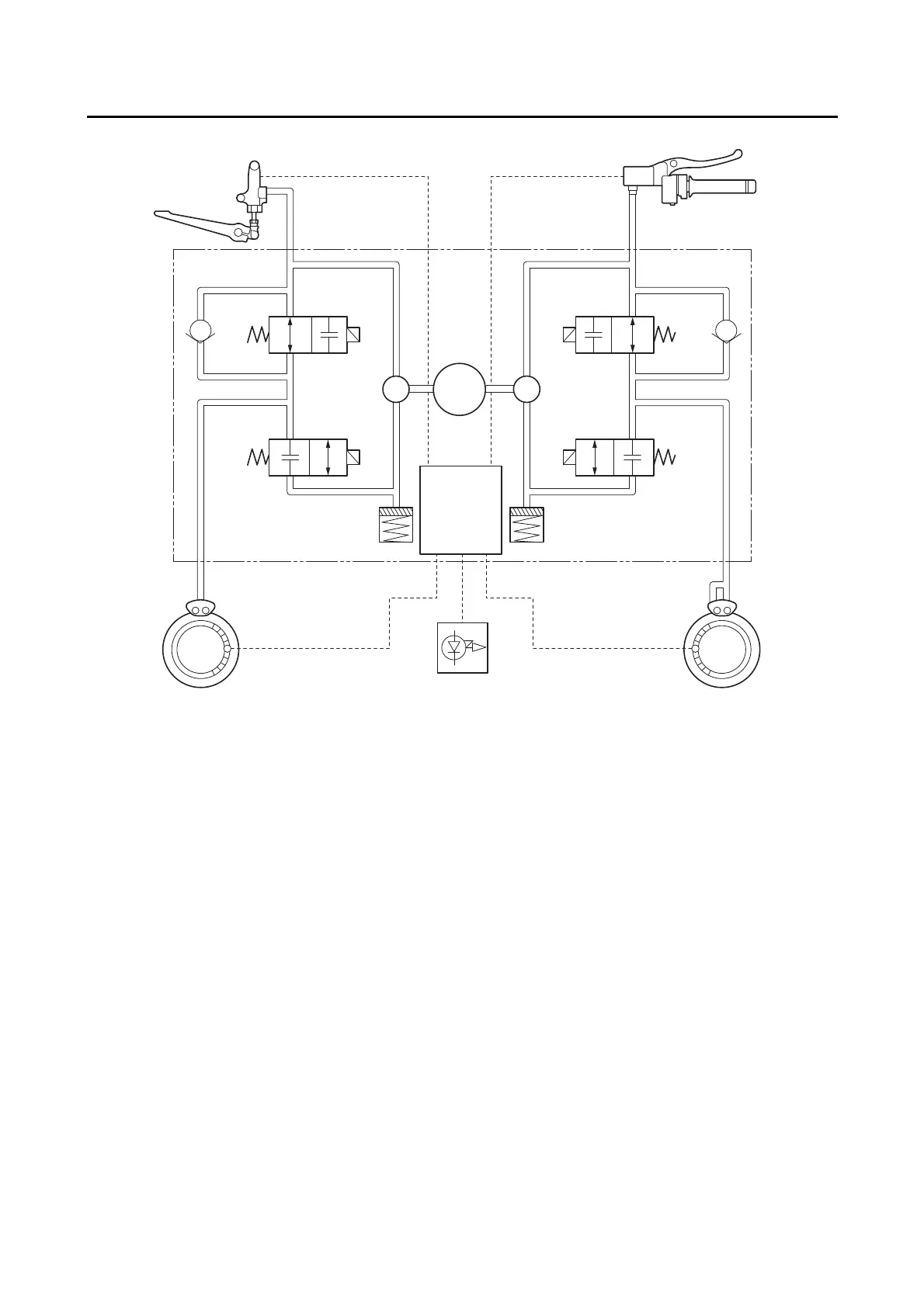
ABS block diagram
EAS30684
ABS COMPONENT FUNCTIONS
Wheel sensors and wheel sensor rotors
Wheel sensors “1” detect the wheel speed and transmit the rotation signal to the ABS ECU.
Each wheel sensor is composed of a permanent magnet and a hall IC. The sensor rotors “2” rotate with
the wheels. The sensor rotors “2” have 40 slots and are installed close to the wheel sensors. As the
sensor rotor rotates, the hall element in the hall IC installed in the wheel sensor generates pulses. The
pulse frequency, which is proportional to the magnetic flux density, is converted into a wave in the hall
IC so that it can be output.
The ABS ECU calculates the wheel rotation speed by detecting the pulse frequency.
1. Rear brake master cylinder
2. Hydraulic unit assembly
3. Front brake master cylinder
4. Inlet solenoid valve
5. ABS motor
6. Hydraulic pump
7. Outlet solenoid valve
8. ABS ECU
9. Buffer chamber
10.Rear brake caliper
11.Rear wheel sensor
12.ABS warning light
13.Front brake caliper
14.Front wheel sensor

 Loading...