ELECTRICAL COMPONENTS
8-131
6. Install:
• Battery
Refer to “GENERAL CHASSIS (1)” on page
4-1.
7. Connect:
• Battery leads
(to the battery terminals)
ECA13630
First, connect the positive battery lead “1”,
and then the negative battery lead “2”.
8. Check:
• Battery terminals
Dirt → Clean with a wire brush.
Loose connection → Connect properly.
9. Lubricate:
• Battery terminals
10.Install:
• Seat bracket
• Rider seat
Refer to “GENERAL CHASSIS (1)” on page
4-1.
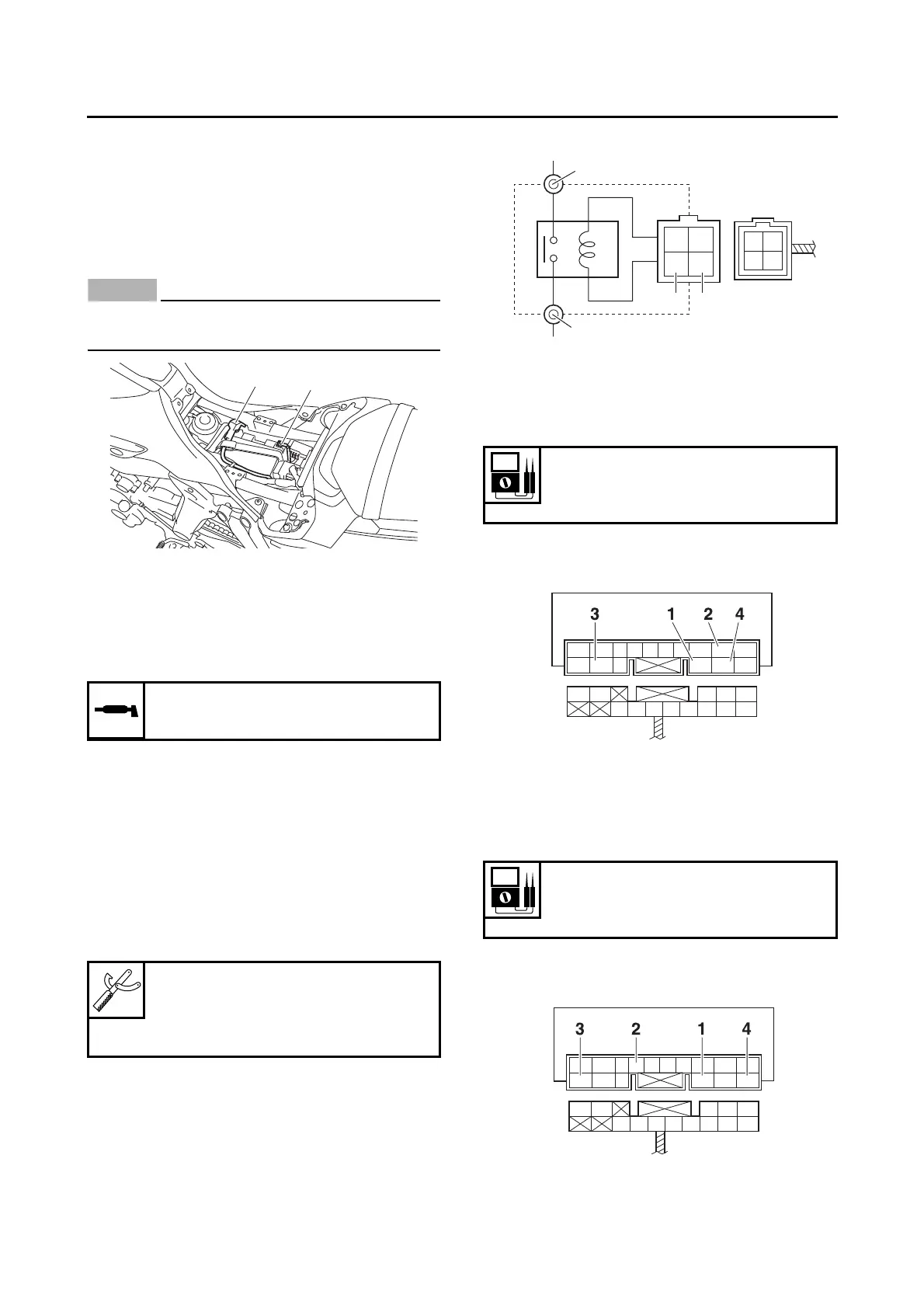
EAS30553
CHECKING THE RELAYS
Check each switch for continuity with the pocket
tester. If the continuity reading is incorrect, re-
place the relay.
1. Disconnect the relay from the wire harness.
2. Connect the pocket tester (Ω × 1) and battery
(12 V) to the relay terminal as shown.
Check the relay operation.
Out of specification → Replace.
Starter relay
Relay unit (starting circuit cut-off relay)
Relay unit (fuel pump relay)
Recommended lubricant
Dielectric grease
Pocket tester
90890-03112
Analog pocket tester
YU-03112-C
1. Positive battery terminal
2. Negative battery terminal
3. Positive tester probe
4. Negative tester probe
Relay operation
Continuity
(between “3” and “4”)
1. Positive battery terminal
2. Negative battery terminal
3. Positive tester probe
4. Negative tester probe
Result
Continuity
(between “3” and “4”)
1. Positive battery terminal
R/WL/WR/BR/LW/L
L/W
L/Y
R/WL/GB/R
B/Y
Sb/W
Sb
R/WL/WR/BR/LW/L
L/W
L/Y
R/WL/GB/R
B/Y
Sb/W
Sb

 Loading...