CONNECTING RODS AND PISTONS
5-80
EAS30750
CHECKING THE CONNECTING RODS
1. Measure:
• Crankshaft-pin-to-big-end-bearing clearance
Out of specification → Replace the big end
bearings.
▼▼▼▼ ▼ ▼▼▼▼▼▼▼▼▼ ▼ ▼▼▼▼ ▼ ▼▼▼▼ ▼ ▼▼▼▼▼▼▼
The following procedure applies to all of the
connecting rods.
ECA13930
Do not interchange the big end bearings and
connecting rods. To obtain the correct
crankshaft-pin-to-big-end-bearing clear-
ance and prevent engine damage, the big
end bearings must be installed in their origi-
nal positions.
a. Clean the big end bearings, crankshaft pins,
and the inside of the connecting rods halves.
b. Install the big end upper bearing into the con-
necting rod and the big end lower bearing into
the connecting rod cap.
Align the projections “a” on the big end bearings
with the notches “b” in the connecting rod and
connecting rod cap.
c. Put a piece of Plastigauge® “1” on the crank-
shaft pin.
d. Assemble the connecting rod halves.
ECA18390
Tighten the connecting rod bolts using the
plastic-region tightening angle method. Al-
ways install new bolts.
• Clean the connecting rod bolts and lubricate
the bolt threads and seats with molybdenum
disulfide oil.
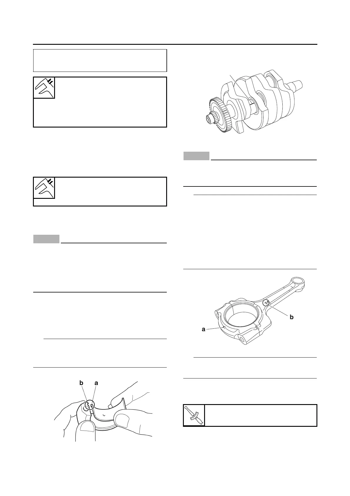
• Make sure that the projection “a” on the con-
necting rod cap faces the same direction as the
“Y” mark “b” on the connecting rod.
• After installing the big end bearing, assemble
the connecting rod and connecting rod cap
without installing them onto the crankshaft.
Install by carrying out the following procedures in
order to assemble in the most suitable condition.
e. Tighten the connecting rod bolt while check-
ing that the sections shown “a” and “b” are
flush with each other by touching the surface.
Piston-pin-to-piston-pin-bore clearance =
Piston pin bore inside diameter “b” –
Piston pin outside diameter “a”
Piston-pin-to-piston-pin-bore
clearance
0.009–0.025 mm (0.0004–0.0010
in)
Limit
0.075 mm (0.0030 in)
Oil clearance
0.027–0.051 mm (0.0011–0.0020
in)
Connecting rod bolt
30 Nm (3.0 m·kgf, 22 ft·lbf)
 Loading...