REAR SHOCK ABSORBER ASSEMBLY
4-93
EAS30826
HANDLING THE REAR SHOCK ABSORBER
EWA13740
This rear shock absorber contains highly
compressed nitrogen gas. Before handling
the rear shock absorber, read and make sure
you understand the following information.
The manufacturer cannot be held responsi-
ble for property damage or personal injury
that may result from improper handling of
the rear shock absorber.
• Do not tamper or attempt to open the rear
shock absorber.
• Do not subject the rear shock absorber to
an open flame or any other source of high
heat. High heat can cause an explosion due
to excessive gas pressure.
• Do not deform or damage the rear shock
absorber in any way. Rear shock absorber
damage will result in poor damping perfor-
mance.
EAS30729
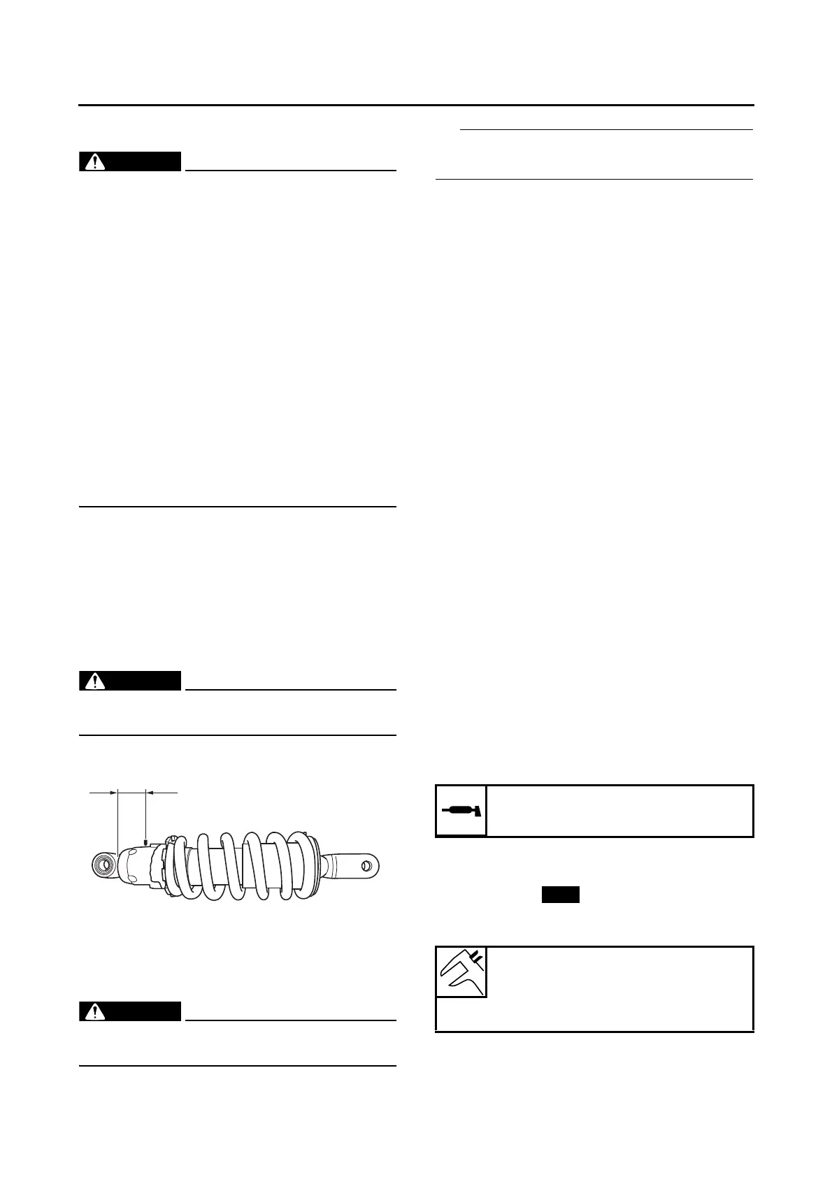
DISPOSING OF A REAR SHOCK ABSORBER
1. Gas pressure must be released before dis-
posing of a rear shock absorber. To release
the gas pressure, drill a 2–3 mm (0.08– 0.12
in) hole through the rear shock absorber at a
point 20–25 mm (0.79–0.98 in) from its end
as shown.
EWA13760
Wear eye protection to prevent eye damage
from released gas or metal chips.
EAS30219
REMOVING THE REAR SHOCK ABSORBER
ASSEMBLY
1. Stand the vehicle on a level surface.
EWA13120
Securely support the vehicle so that there is
no danger of it falling over.
Place the vehicle on a suitable stand so that the
rear wheel is elevated.
EAS30220
CHECKING THE REAR SHOCK ABSORBER
ASSEMBLY
1. Check:
• Rear shock absorber rod
Bends/damage → Replace the rear shock
absorber assembly.
• Rear shock absorber assembly
Gas leaks → Replace the rear shock absorb-
er assembly.
•Spring
Damage/wear → Replace the rear shock ab-
sorber assembly.
•Bolts
Bends/damage/wear → Replace.
EAS31112
CHECKING THE RELAY ARM
1. Check:
• Relay arm
Damage/wear → Replace.
2. Check:
• Bearings
• Oil seals
Damage/pitting → Replace.
3. Check:
• Collars
Damage/scratches → Replace.
EAS30222
INSTALLING THE RELAY ARM
1. Lubricate:
• Spacers
• Bearings
2. Install:
• Bearings “1”
• Oil seals “2”
• Spacers “3”
(to the relay arm “4”)
Recommended lubricant
Lithium-soap-based grease
Installed depth “a”
4.0 mm (0.16 in)
Installed depth “b”
More than 0.3 mm (0.01 in)

 Loading...