CAMSHAFTS
5-17
EAS30256
REMOVING THE CAMSHAFTS
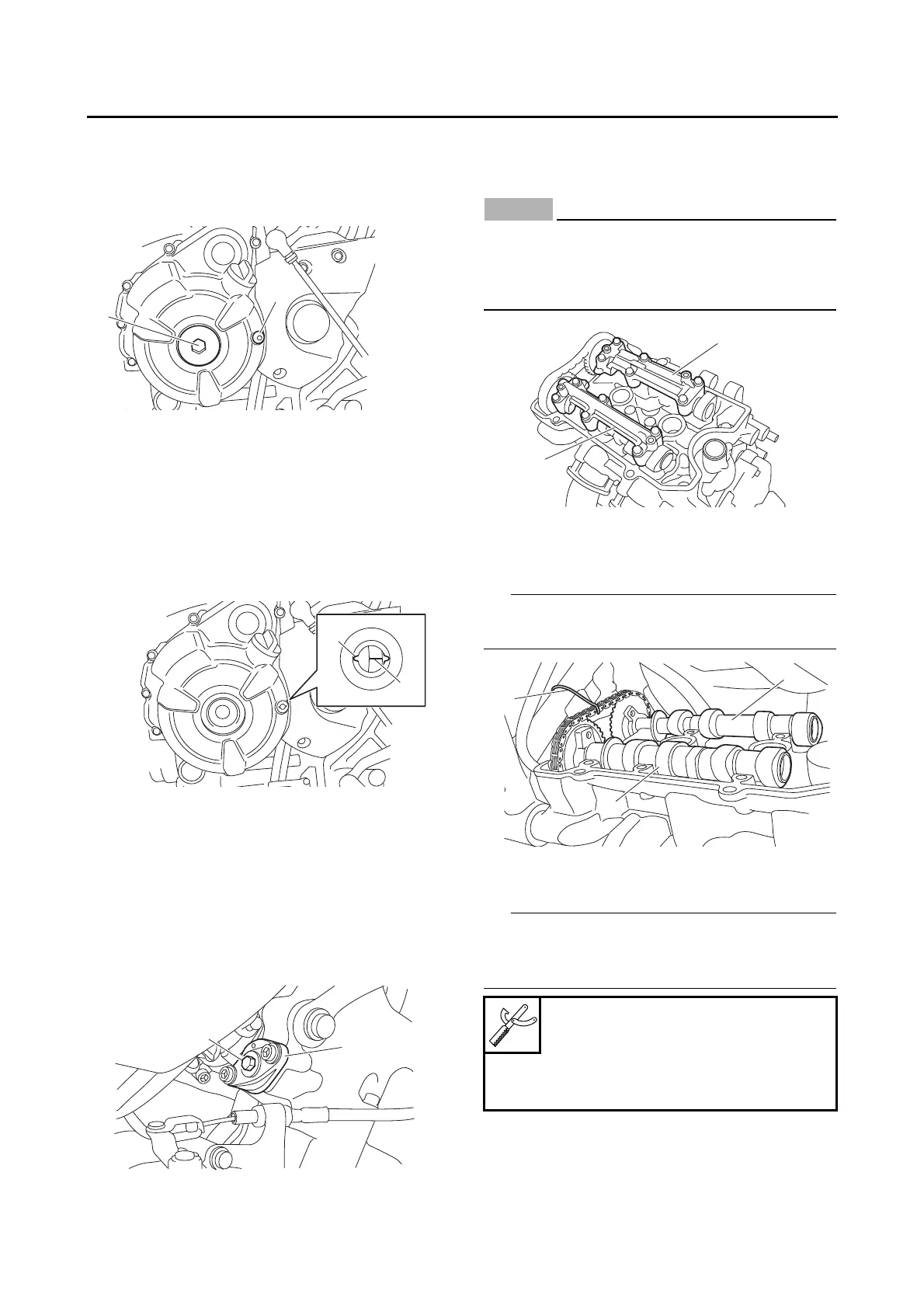
1. Remove:
• Crankshaft end cover “1”
• Timing mark accessing bolt “2”
2. Align:
• Mark “a” on the generator rotor
(with the slot “b” in the generator rotor cover)
▼▼▼▼ ▼ ▼▼▼▼▼▼▼▼▼ ▼ ▼▼▼▼ ▼ ▼▼▼▼ ▼ ▼▼▼▼▼▼▼
a. Turn the crankshaft counterclockwise.
b. When piston #1 is at TDC on the exhaust
stroke, align the TDC mark “a” on the gener-
ator rotor with the slot “b” in the generator ro-
tor cover.
▲▲▲▲ ▲ ▲▲▲▲▲▲▲▲▲ ▲ ▲▲▲▲ ▲ ▲▲▲▲ ▲ ▲▲▲▲▲▲▲
3. Remove:
• Timing chain tensioner “1”
• Timing chain tensioner gasket
▼▼▼▼ ▼ ▼▼▼▼▼▼▼▼▼ ▼ ▼▼▼▼ ▼ ▼▼▼▼ ▼ ▼▼▼▼▼▼▼
a. Insert the hexagon wrench “2” (part No.:
1WS-12228-00) into the timing chain tension-
er.
b. Remove the timing chain tensioner.
▲▲▲▲ ▲ ▲▲▲▲▲▲▲▲▲ ▲ ▲▲▲▲ ▲ ▲▲▲▲ ▲ ▲▲▲▲▲▲▲
4. Remove:
• Intake camshaft cap “1”
• Exhaust camshaft cap “2”
ECA13720
To prevent damage to the cylinder head,
camshafts or camshaft caps, loosen the
camshaft cap bolts in stages and in a criss-
cross pattern, working from the outside in.
5. Remove:
• Intake camshaft “1”
• Exhaust camshaft “2”
To prevent the timing chain from falling into the
crankcase, fasten it with a wire “3”.
6. Remove:
• Intake camshaft sprocket “1”
While holding the intake camshaft sprocket with
the rotor holding tool “2”, loosen the intake cam-
shaft sprocket bolts.
Rotor holding tool
90890-01235
Universal magneto and rotor
holder
YU-01235

 Loading...