CYLINDER HEAD
5-30
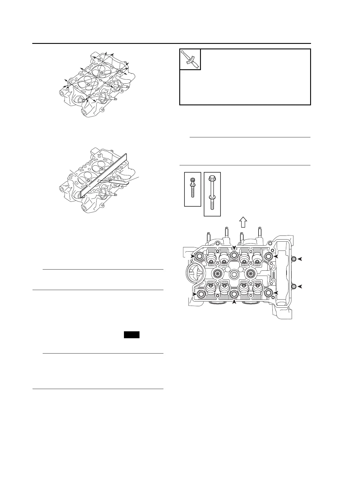
▼▼▼▼ ▼ ▼▼▼▼▼▼▼▼▼ ▼ ▼▼▼▼ ▼ ▼▼▼▼ ▼ ▼▼▼▼▼▼▼
a. Place a straightedge “1” and a thickness
gauge “2” across the cylinder head.
b. Measure the warpage.
c. If the limit is exceeded, resurface the cylinder
head as follows.
d. Place a 400–600 grit wet sandpaper on the
surface plate and resurface the cylinder head
using a figure-eight sanding pattern.
To ensure an even surface, rotate the cylinder
head several times.
▲▲▲▲ ▲ ▲▲▲▲▲▲▲▲▲ ▲ ▲▲▲▲ ▲ ▲▲▲▲ ▲ ▲▲▲▲▲▲▲
EAS30282
INSTALLING THE CYLINDER HEAD
1. Install:
• Cylinder head
• Cylinder head bolt (M10) (×6)
• Cylinder head bolt (M6) (×2)
• Pass the timing chain through the timing chain
cavity.
• Lubricate the cylinder head bolt (M10) threads
and mating surface with engine oil.
2. Tighten:
• Cylinder head bolts “1”–“6”
• Cylinder head bolts “7”, “8”
* Following the tightening order, loosen the
bolt one by one, and then retighten it to the
specific torque.
Tighten the cylinder head bolts in the tightening
sequence as shown and torque them in 4 stag-
es.
Cylinder head bolt (“1”–“6”)
1st: 10 Nm (1.0 m·kgf, 7.2 ft·lbf)
2nd: 40 Nm (4.0 m·kgf, 29 ft·lbf)
*3rd: 20 Nm (2.0 m·kgf, 14 ft·lbf)
Specified angle 90°
Cylinder head bolt (“7”, “8”)
10 Nm (1.0 m·kgf, 7.2 ft·lbf)

 Loading...