GENERAL CHASSIS (5)
4-17
EAS31108
REMOVING THE ECU (engine control unit)
1. Disconnect:
• ECU coupler “1”
While pushing the portion “a” of the ECU cou-
pler, move the lock lever “b” in the direction of
the arrow shown to disconnect the coupler.
EAS31109
INSTALLING THE ECU (engine control unit)
1. Connect:
• ECU coupler “1”
Connect the ECU coupler, and then push the
lock lever “a” of the coupler in the direction of the
arrow shown.
EAS31129
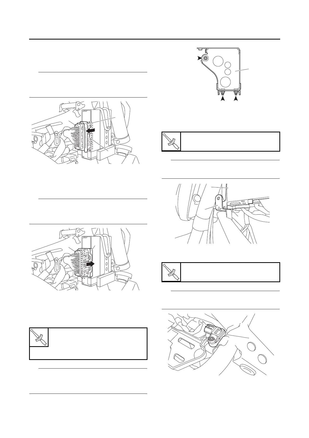
INSTALLING THE ELECTRICAL
COMPONENTS TRAYS
1. Install:
• Electrical components tray 2 “1”
Tighten the electrical components tray 2 nuts
and bolt in the proper tightening sequence as
shown.
2. Install:
• Fuel tank cover bracket “1”
• Electrical components tray 1 “2”
Make sure that the projection “a” on the fuel tank
cover bracket contacts the frame.
3. Install:
• Intake air pressure sensor “1”
Make sure that the intake air pressure sensor
contacts the frame.
Electrical components tray 2 nut
7 Nm (0.7 m·kgf, 5.1 ft·lbf)
Electrical components tray 2 bolt
7 Nm (0.7 m·kgf, 5.1 ft·lbf)
Electrical components tray 1 bolt
7 Nm (0.7 m·kgf, 5.1 ft·lbf)
Intake air pressure sensor bolt
3.8 Nm (0.38 m·kgf, 2.8 ft·lbf)

 Loading...